1,886
Views
26
CrossRef citations to date
0
Altmetric
Articles

Optimization of centrifugally spun thermoplastic polyurethane nanofibers for air filtration applications

, & ORCID Icon
Pages 515-523 | Received 09 Sep 2017, Accepted 02 Jan 2018, Published online: 20 Feb 2018

Figures & data

Figure 1. The schematic of the Nanocentrino L1.0 system.

Figure 1. The schematic of the Nanocentrino L1.0 system.

Table 1. Design of experiment.

Figure 2. SEM images and diameter distribution of the samples produced with 16G needles. (a) sample 1 (4000 rpm and 10 wt%), (b) sample 2 (8000 rpm and 15 wt%), and (c) sample 3 (12,000 rpm and 20 wt%).
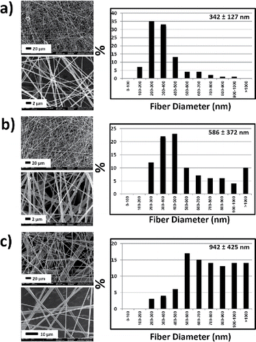
Figure 2. SEM images and diameter distribution of the samples produced with 16G needles. (a) sample 1 (4000 rpm and 10 wt%), (b) sample 2 (8000 rpm and 15 wt%), and (c) sample 3 (12,000 rpm and 20 wt%).

Figure 3. SEM images and diameter distribution of the samples produced with 18G needles. (a) sample 4 (4000 rpm and 15 wt%), (b) sample 5 (8000 rpm and 20 wt%), and (c) sample 6 (12,000 rpm and 10 wt%).
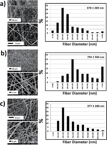
Figure 3. SEM images and diameter distribution of the samples produced with 18G needles. (a) sample 4 (4000 rpm and 15 wt%), (b) sample 5 (8000 rpm and 20 wt%), and (c) sample 6 (12,000 rpm and 10 wt%).

Figure 4. SEM images and diameter distribution of the samples produced with 22G needles. (a) sample 7 (4000 rpm and 20 wt%), (b) sample 8 (8000 rpm and 10 wt %), and (c) sample 9 (12,000 rpm and 15 wt%).
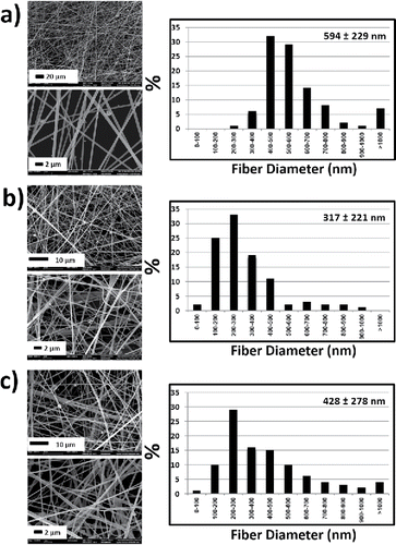
Figure 4. SEM images and diameter distribution of the samples produced with 22G needles. (a) sample 7 (4000 rpm and 20 wt%), (b) sample 8 (8000 rpm and 10 wt %), and (c) sample 9 (12,000 rpm and 15 wt%).

Table 2. S/N ratios of design factors: smaller is better.

Figure 5. Average fiber diameters corresponding to the experiments. The boundaries in box plot represent the upper (75th %) and lower (25th %) quartiles. The line represents the median and the plus sign also represents the mean value of fiber diameters.
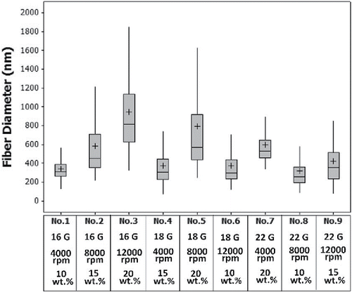
Figure 5. Average fiber diameters corresponding to the experiments. The boundaries in box plot represent the upper (75th %) and lower (25th %) quartiles. The line represents the median and the plus sign also represents the mean value of fiber diameters.

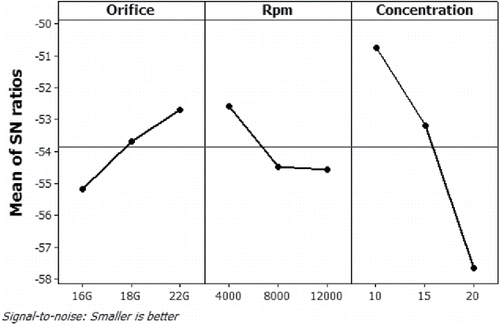
Figure 6. S/N ratio graphs for each design factors with levels.

Figure 6. S/N ratio graphs for each design factors with levels.

Table 3. Analysis of variance for means.

Figure 7. Effect of different C-spin parameters on the average fiber diameters. (a) Orifice diameter and rotational speed, (b) orifice diameter and solution concentration, and (c) rotational speed and solution concentration. The 3rd process parameters which do not appear in graphs have also an effect on diameters.
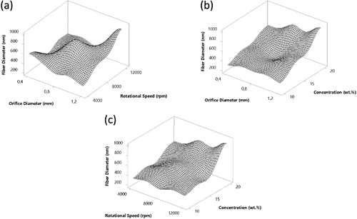
Figure 7. Effect of different C-spin parameters on the average fiber diameters. (a) Orifice diameter and rotational speed, (b) orifice diameter and solution concentration, and (c) rotational speed and solution concentration. The 3rd process parameters which do not appear in graphs have also an effect on diameters.

Figure 8. SEM images and fiber diameter distributions of the optimum condition (22G, 4000 rpm, 10 wt%), respectively.
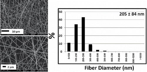
Figure 8. SEM images and fiber diameter distributions of the optimum condition (22G, 4000 rpm, 10 wt%), respectively.

Figure 9. Average fiber diameters corresponding to all the 9 experiments, sample 8, and the experiment at the optimum condition, respectively. The boundaries in box plot represent the upper (75th%) and lower (25th%) quartiles. The line and plus sign represents median and represent the mean value of fiber diameters, respectively.
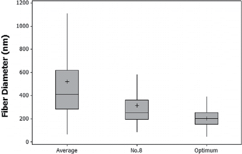
Figure 9. Average fiber diameters corresponding to all the 9 experiments, sample 8, and the experiment at the optimum condition, respectively. The boundaries in box plot represent the upper (75th%) and lower (25th%) quartiles. The line and plus sign represents median and represent the mean value of fiber diameters, respectively.
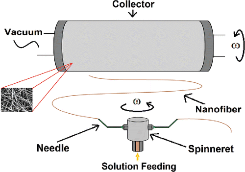
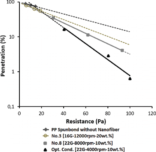
Figure 10. Percentage of penetration versus resistance curves of fibrous samples challenged with 0.3 µm Emery 3004 particles.

Figure 10. Percentage of penetration versus resistance curves of fibrous samples challenged with 0.3 µm Emery 3004 particles.

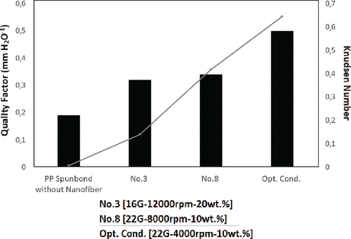
Figure 11. Quality factor values of different triple layer samples challenged with Emery 3004 aerosols. The Knudsen number for PP spunbond without NF is 0.007, while No 3 is 0.140, No 8 is 0.416, and Opt. Cond. is 0.644.

Figure 11. Quality factor values of different triple layer samples challenged with Emery 3004 aerosols. The Knudsen number for PP spunbond without NF is 0.007, while No 3 is 0.140, No 8 is 0.416, and Opt. Cond. is 0.644.

Reprints and Corporate Permissions

Please note: Selecting permissions does not provide access to the full text of the article, please see our help page How do I view content?

To request a reprint or corporate permissions for this article, please click on the relevant link below:

Academic Permissions

Please note: Selecting permissions does not provide access to the full text of the article, please see our help page How do I view content?

Obtain permissions instantly via Rightslink by clicking on the button below:

If you are unable to obtain permissions via Rightslink, please complete and submit this Permissions form. For more information, please visit our Permissions help page.