Figures & data
Figure 1. Schematics of the Aerosol Jet® direct-write system: (1) atomizer that generates mist of microdroplets of functional inks; (2) mist transport-conditioning channel that delivers a concentrated mist of ink microdroplets; (3) deposition head to form high-speed collimated mist stream through an aerodynamic focusing nozzle with sheath gas (with arrows indicate the mist carrier gas inlet and nozzle sheath gas inlet). The photography on right shows visualized mist stream from the deposition nozzle.
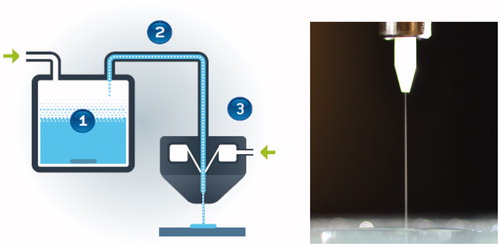
Figure 2. Free-jet mist flows of D = 0.3 mm at Re = 293, 586, and 1171 (for Q = 60, 120, and 240 sccm) with sheath-to-mist ratio Y = 1:1. The length of the white ceramic nozzle tip outside the stainless steel holder is 4 mm, which can effectively serve as a scale reference.
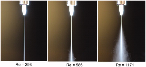
Figure 3. As but at Re = 732 (for Q = 150 sccm) with sheath-to-mist ratio Y = 2:1, 1:1, and 1:2 having corresponding breakdown length of 47, 27, and 20, respectively.
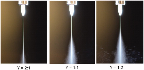
Figure 4. Impinging-jet mist flows of D = 0.3 mm at Re = 1171, 878, and 586 (for Q = 240, 180, and 120 sccm) with sheath-to-mist ratio Y = 1:1, for S = 10 mm.
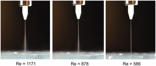
Figure 5. As but for S = 6 mm at Re = 732, 1171, and 1464 (for Q = 150, 240, and 300 sccm).
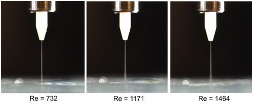
Figure 6. Free-jet mist flows of D = 0.15 mm at Re = 390, 586, and 878 (for Q = 40, 60, and 90 sccm) with sheath-to-mist ratio Y = 1:1. The length of the white ceramic nozzle tip outside the stainless steel holder is 4 mm, which can effectively serve as a scale reference.
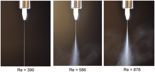
Figure 7. Impinging-jet mist flows of D = 0.15 mm at Re = 1171, 878, and 586 (for Q = 120, 90, and 60 sccm) with sheath-to-mist ratio Y = 1:1, for S = 6 mm.
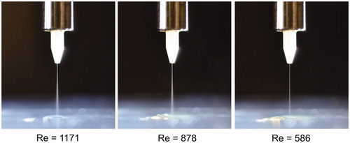
Figure 8. As but for S = 4 mm at Re = 1464, 1171, and 878 (for Q = 150, 120, and 90 sccm).
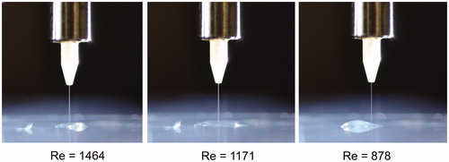
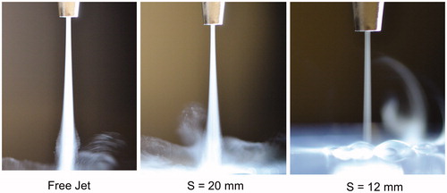
Figure 9. Mist flows of D = 1.0 mm at Re = 1464 (for Q = 1000 sccm) with sheath-to-mist ratio Y = 1:1 for different standoff distances. The outer diameter of the nozzle tip is 2.75 mm, which can effectively serve as a scale reference.
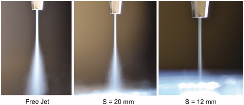
Figure 10. As but at Re = 293 (for Q = 200 sccm).