
Figures & data
Figure 1. The purification module in a kitchen exhaust hood.
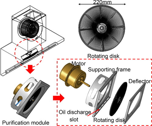
Figure 2. (a) Wind tunnel test rig for the rotating disk. (b) Oil particle generator. (c) Velocity measurement points at Sections #1 and #2.
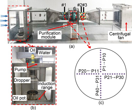
Table 1. Instrument specifications.
Figure 3. Mean value of mass concentration and size distribution of the oil droplets from eight repeated measurements.
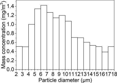
Figure 4. (a) Purification module used for simulations. (b) Grid-independence test. (c) Grid distribution of the vertical section in the module.
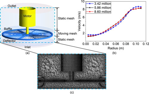
Figure 5. (a) Velocity measured in the wind tunnel at Section #2. (b) Comparison of the air velocity profiles predicted by the three turbulence models with the experimental data at Section #2. (c) Comparison of experimental and simulated capture efficiency versus particle diameter.
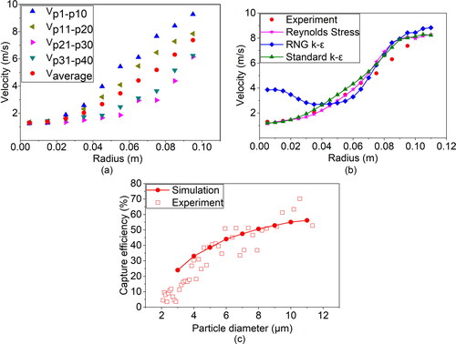
Figure 6. (a) Computed air velocity distribution at Section #2 in the downstream region and (b) computed air velocity components in the radial direction.
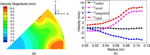
Figure 7. Trajectories of particles with different diameters: (a) 3 D view (b) 5 µm (c) 10 µm (d) 15 µm and (e) 20 µm.
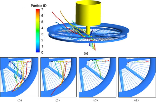
Figure 8. Particle capture efficiency vs. (a) disk rotation speeds when the airflow velocity was 4.00 m/s. (b) airflow velocity when the disk rotated at 2050 r/min. (c) disk components.
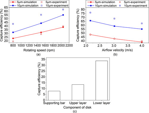
Figure 9. Improvement methods: (a) adding more wires and (b) using a double disk.
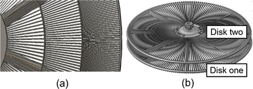
Table 2. Improvement in capture efficiency by adding more wires to the rotating disk.