Figures & data
FIG. 1 Side-view schematic diagram of the experimental apparatus (not to scale). Straight duct sections are square in crosssection, 15 cm on a side by 152 cm long. The inset shows a close-up side view of an S-connector between two duct sections.
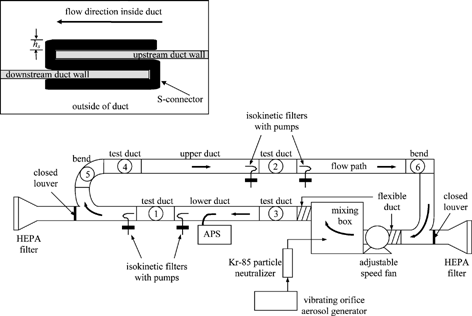
FIG. 2 Dimensionless deposition velocities to S-connectors on the ceiling, wall, and floor at air speeds of (a) 2.2 m/s, (b) 5.3 m/s, and (c) 9.0 m/s.
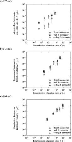
FIG. 3 S-connector deposition fraction versus connector Stokes number for S-connectors on the ceiling, wall, and floor at the three nominal air speeds.
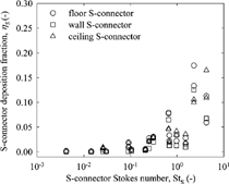
TABLE 1 Average S-connector deposition fractions in the bare steel duct systemFootnote a
FIG. 4 Penetration through (a) bend 5 and (b) bend 6 versus bend Stokes number for all air speeds in both the bare steel and insulated systems.
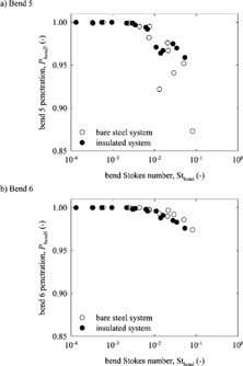
FIG. 5 Composite dimensionless deposition velocities in (a) bend 5 and (b) bend 6 compared to dimensionless deposition velocities in straight steel ducts at nominal air speeds of 2.2 m/s, 5.3 m/s, and 9.0 m/s.
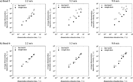
TABLE 2 Measured bend penetrations for all experimentsFootnote a
TABLE 3 Dimensionless deposition velocities for all panels in test duct 4 for all experimentsFootnote a Footnote b
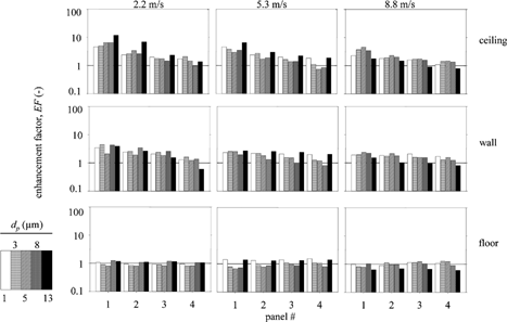
FIG. 6 Enhancement factors at the ceiling, wall, and floor at panels in duct 4 in the bare steel system at three air speeds. Panels measure approximately 10 cm × 20 cm and are centered 30, 61, 91, and 122 cm downstream from the leading edge of a duct. See CitationSippola and Nazaroff (2004) for additional details.
FIG. 7 Enhancement factors at the ceiling, wall, and floor at panels in duct 4 in the insulated system at three air speeds. Panels measure approximately 10 cm × 20 cm and are centered 30, 61, 91, and 122 cm downstream from the leading edge of a duct. See CitationSippola and Nazaroff (2004) for additional details.