4,689
Views
592
CrossRef citations to date
0
Altmetric
Original Articles

A Continuous-Flow Streamwise Thermal-Gradient CCN Chamber for Atmospheric Measurements

&
Pages 206-221 | Received 08 Jul 2004, Accepted 03 Dec 2004, Published online: 26 Mar 2010

Figures & data

Fig. 1 (a) The alternating gradient technique for repeating hot/cold sections in cylindrical symmetry. The upper graph shows the alternating temperature gradient (horizontal bars) and the development of the supersaturation profile near the centerline of the chamber (multiple sinusoidal lines). Notice that the minimum saturation ratio briefly drops below 1 (<0% supersaturation) just after the cold sections. Droplets momentarily evaporate during this period. The lower graph illustrates the contours of the supersaturation profile in the radial, r, and streamwise, z, dimensions. The centerline is at r = 0. The dashed line approximates the aerosol boundary in the column. (b) The linear thermal-gradient technique in cylindrical symmetry. The upper graph shows the linear temperature gradient (straight line) and the development of the uniform supersaturation profile near the centerline of the chamber. Notice that unlike (a), the supersaturation is always positive (or SR > 1) throughout most of the instrument. The lower graph illustrates the contours of the supersaturation profile in the radial and streamwise dimensions. The centerline is at r = 0. The dashed line approximates the aerosol boundary in the column.
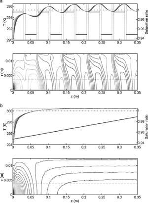
Fig. 1 (a) The alternating gradient technique for repeating hot/cold sections in cylindrical symmetry. The upper graph shows the alternating temperature gradient (horizontal bars) and the development of the supersaturation profile near the centerline of the chamber (multiple sinusoidal lines). Notice that the minimum saturation ratio briefly drops below 1 (<0% supersaturation) just after the cold sections. Droplets momentarily evaporate during this period. The lower graph illustrates the contours of the supersaturation profile in the radial, r, and streamwise, z, dimensions. The centerline is at r = 0. The dashed line approximates the aerosol boundary in the column. (b) The linear thermal-gradient technique in cylindrical symmetry. The upper graph shows the linear temperature gradient (straight line) and the development of the uniform supersaturation profile near the centerline of the chamber. Notice that unlike (a), the supersaturation is always positive (or SR > 1) throughout most of the instrument. The lower graph illustrates the contours of the supersaturation profile in the radial and streamwise dimensions. The centerline is at r = 0. The dashed line approximates the aerosol boundary in the column.

Fig. 2Operational and flow schematic of the streamwise thermal gradient CCN instrument.

Fig. 2Operational and flow schematic of the streamwise thermal gradient CCN instrument.

FIG. 3 Schematic of the geometry used for the analysis of the section “Theory of Operation.”

FIG. 3 Schematic of the geometry used for the analysis of the section “Theory of Operation.”

Table 1 Transfer coefficients and source terms for the gas-phase equations described in the section “Fully-Coupled Instrument Model”

Fig. 4 Predictions of supersaturation based on fully-coupled model simulations for individual variables at conditions similar to normal operation. The error bars on the fully-coupled simulations represent one-sigma variations to the mean centerline supersaturation. Supersaturation is defined as (S R − 1) × 100%.
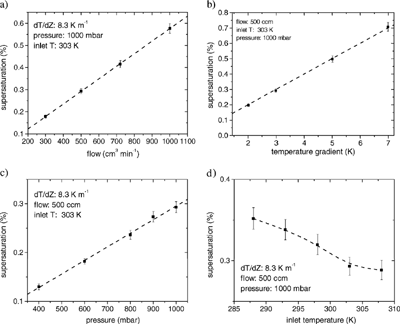
Fig. 4 Predictions of supersaturation based on fully-coupled model simulations for individual variables at conditions similar to normal operation. The error bars on the fully-coupled simulations represent one-sigma variations to the mean centerline supersaturation. Supersaturation is defined as (S R − 1) × 100%.

Fig. 5Model simulations of streamline deviations in the chamber as a function of column radius for a range of flow rates and temperature gradients.
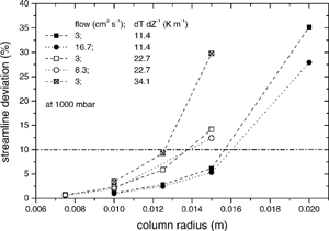
Fig. 5Model simulations of streamline deviations in the chamber as a function of column radius for a range of flow rates and temperature gradients.

Fig. 6Calibration and growth curves of CCN at different operating conditions. The dry diameters are based on median diameters from . Aerosol at a particular dry diameter is considered activated when the ratio of CCN (i.e., droplets greater than 1 μm) to total aerosol is greater than 0.5. The shoulders result from multiple charge particles from the DMA classification.
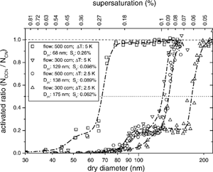
Fig. 6Calibration and growth curves of CCN at different operating conditions. The dry diameters are based on median diameters from Figure 6. Aerosol at a particular dry diameter is considered activated when the ratio of CCN (i.e., droplets greater than 1 μm) to total aerosol is greater than 0.5. The shoulders result from multiple charge particles from the DMA classification.

Fig. 7 Polydisperse dry aerosol distributions of (NH4)2SO4. The vertical dashed line shows the calibrated critical diameter at 500 cm3 min−1 and a measured temperature gradient of 5 K. Particle sizes larger than the vertical dashed line are expected to be CCN active. The actual values of the verticalaxis are not shown because they change after each cycle.
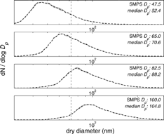
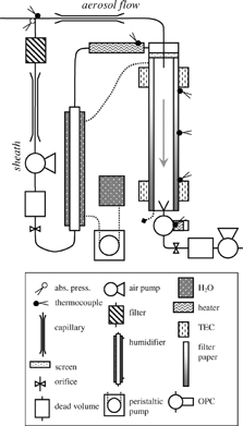
Fig. 7 Polydisperse dry aerosol distributions of (NH4)2SO4. The vertical dashed line shows the calibrated critical diameter at 500 cm3 min−1 and a measured temperature gradient of 5 K. Particle sizes larger than the vertical dashed line are expected to be CCN active. The actual values of the verticalaxis are not shown because they change after each cycle.

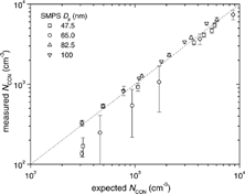
Fig 8 Measured versus calculated CCN concentration using the polydisperse dry aerosol distributions of known composition. SMPS D p represents the desired diameter of each polydisperse size distribution. Actual median diameters were calculated during analysis.

Fig 8 Measured versus calculated CCN concentration using the polydisperse dry aerosol distributions of known composition. SMPS D p represents the desired diameter of each polydisperse size distribution. Actual median diameters were calculated during analysis.

Reprints and Corporate Permissions

Please note: Selecting permissions does not provide access to the full text of the article, please see our help page How do I view content?

To request a reprint or corporate permissions for this article, please click on the relevant link below:

Academic Permissions

Please note: Selecting permissions does not provide access to the full text of the article, please see our help page How do I view content?

Obtain permissions instantly via Rightslink by clicking on the button below:

If you are unable to obtain permissions via Rightslink, please complete and submit this Permissions form. For more information, please visit our Permissions help page.