Figures & data
Table 1. Correction method, magnitude of rotational corrections, and set-up error for six investigated set-up strategies.
Figure 1. Cumulative distributions of the 3D root-mean-square error on the markers for all the set-up strategies (a) and the 2D error (RL-AP) on the spinal cord for strategies 1 and 3–6 (b). The vertical line indicates 10 mm which is commonly used as planning risk volume (PRV) margin.
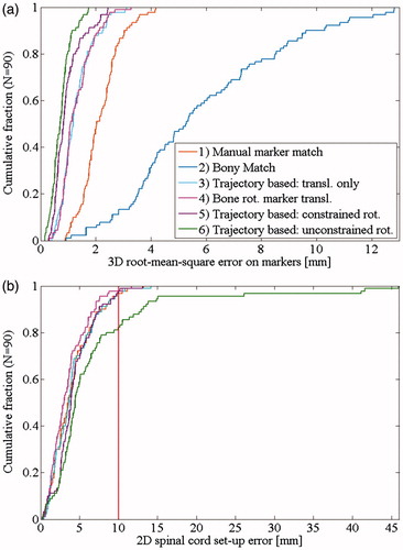
Figure 2. Internal target motion per fraction for: (a) Eight patients with large motion range (>1.5 cm/5°). (b) Seven patients with large mean internal motion (>1.5 cm/5°). Patient treated without abdominal compression are shown with a full symbol.
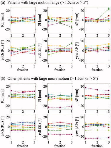
Table 2. Absolute internal interfraction motion of the marker constellation relative to bony anatomy for 90 CBCTs and range of internal motion for 27 patients when compared to the planning CT.
Table 3. Spinal cord set-up error for the marker-based set-up strategies.
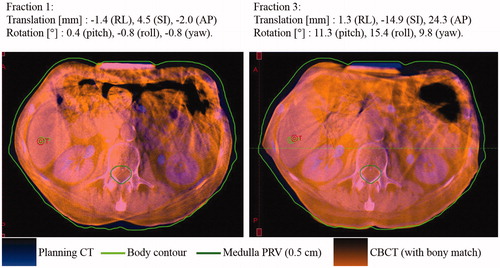
Figure 3. Patient with large marker constellation rotation relative to bony anatomy at fraction 3, possibly due to a poorly reproduced abdominal compression position. The CBCT is registered to the planning CT based on bony anatomy. The markers are not visible on this image because they are implanted cranially to the abdominal compression. The specified translations and rotations are the internal marker constellation motion with respect to the bony anatomy as compared to the planning CT.