Figures & data
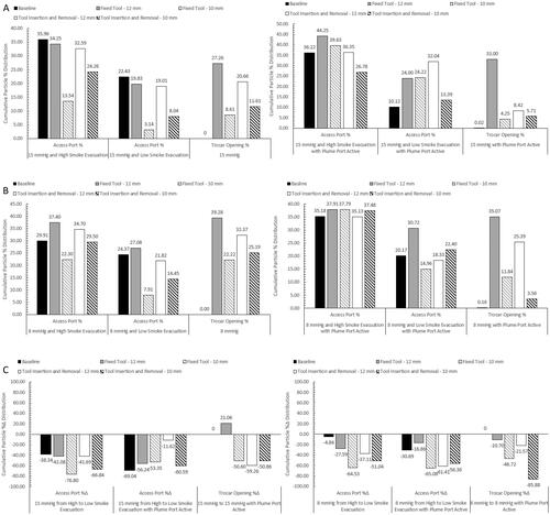
Figure 1. Schematics of the various test setups used for particle and flow measurements. (A) Simulated laparoscopic cavity with the equipment surface layout, (B) Simulated laparoscopic cavity test setup for standardised flow rate measurement, (C) Test setup for testing with a laparoscopic tool fixed within the Access Port or trocar, and (D) Step through of the laparoscopic tool position during automated insertion and removal through the Access Port or trocar. Schematic shows the tool position at 0 and 30–60 s, and at 15 s.
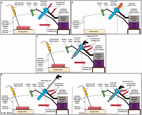
Figure 2. (A) Image showing the simulated laparoscopic cavity with the equipment surface layout, (B) Simulated laparoscopic cavity test setup for standardised flow rate measurement, (C) Test setup for testing with a laparoscopic tool fixed within the Access Port or trocar, and (D) Step through of the laparoscopic tool position during automated insertion and removal through the Access Port or trocar.
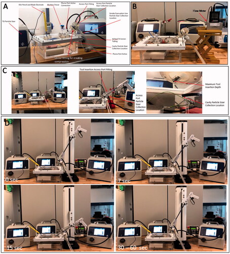
Figure 3. Cross sectional schematics of the fittings used for flow rate and SSPM measurement with the particle sizers at the opening of the Access Port and trocar, with laparoscopic tool insertion, and from the smoke evacuation line of the tri-lumen tube set.
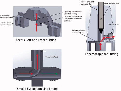
Table 1. Average AirSeal access port flow rates.
Figure 4. Standardised flow rate graph showing the fluctuations of gas flow at the top of the Access Port with and without the suction assist device active. Graph utilises a 5-point moving average.
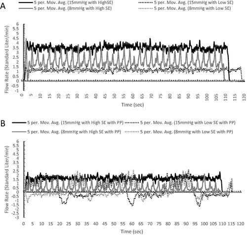
Figure 5. Bar graphs (A and B) show the cumulative particle % distribution over the 15 min measurement time and the table shows the time until ≥95% particle reduction from each measurement location when testing with the AirSeal® System at 15 mmHg. The cumulative particle % distribution totals for each test setup and measurement location are reached, at least 95% of the total, at the evacuation time shown in the table.
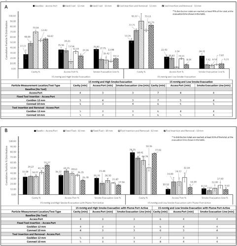
Figure 6. Bar graphs (A and B) show the cumulative particle % distribution over the 15 min measurement time and the table shows the time until ≥95% particle reduction from each measurement location when testing with the AirSeal® System at 8 mmHg. The cumulative particle % distribution totals for each test setup and measurement location are reached, at least 95% of the total, at the evacuation time shown in the table.
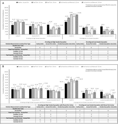
Table 2. Range of particle diameters associated with midpoint diameter.
Figure 7. Bar graphs (A and B) show the cumulative particle % distribution over the 15 min measurement time and the table shows the time until ≥95% particle reduction from each measurement location when testing with the traditional insufflation and access system. The cumulative particle % distribution totals for each test setup and measurement location are reached, at least 95% of the total, at the evacuation time shown in the table.
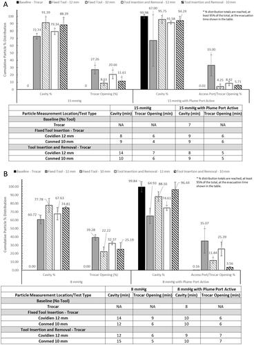
Figure 8. Representative graphs of the particle diameter concentration profile and percent distribution of each diameter seen during surgical smoke generation within the (A) SLC, (B) at the opening of the Access Port, and (C) within the smoke evacuation line. Data shown uses results from testing at 15 mmHg with High and Low smoke evacuation rates, and at Low smoke evacuation rate with the SAS.
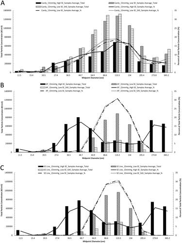
Figure 9. Bar graphs (A and B) show the cumulative particle %Δ distribution over the 15 min measurement time for either insufflation and access system.
*Not statistically significant, Paired T-test p value ≥ 0.10
**Borderline statistically significant, Paired T-test 0.05 ≥ p value ≥ 0.10
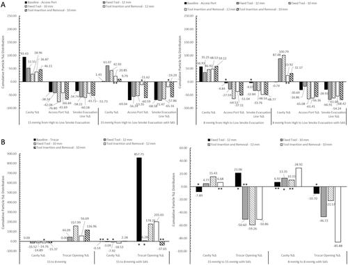
Figure 10. Particle percent distribution (A and B) and percent change distribution (C) bar graphs of Access Port and trocar opening only at 15 and 8 mmHg cavity pressure.