1,769
Views
16
CrossRef citations to date
0
Altmetric
Original Articles

Sintering Process and Mechanical Property of MWCNTs/HDPE Bulk Composite

, &
Pages 821-826 | Published online: 22 Jul 2009

Figures & data

FIG. 1 SEM image of the received MWCNTs.

FIG. 1 SEM image of the received MWCNTs.

FIG. 2 Procedures for preparing MWCNTs/HDPE bulk composite.

FIG. 2 Procedures for preparing MWCNTs/HDPE bulk composite.

FIG. 3 SEM image of carbon nanotubes were uniformly dispersed and implanted within HDPE powder.

FIG. 3 SEM image of carbon nanotubes were uniformly dispersed and implanted within HDPE powder.

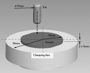
FIG. 4 Schematic of small pin-on-disk test clamping dies apparatus.

FIG. 4 Schematic of small pin-on-disk test clamping dies apparatus.

FIG. 5 (a) The consolidated pure HDPE and MWCNTs/HDPE composites obtained after hot compacting sintering process and (b) SEM image of a 4.0 wt% MWCNTs/HDPE nanocomposite, which shows a homogeneous distribution of carbon nanotubes.
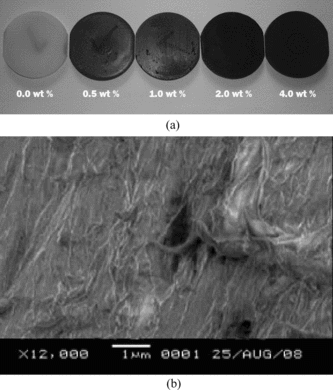
FIG. 5 (a) The consolidated pure HDPE and MWCNTs/HDPE composites obtained after hot compacting sintering process and (b) SEM image of a 4.0 wt% MWCNTs/HDPE nanocomposite, which shows a homogeneous distribution of carbon nanotubes.

FIG. 6 (a) The variation of Shore-D hardness of MWCNTs/HDPE composites with varying the weight fraction of carbon nanotubes and (b) the variation of wear properties of MWCNTs/HDPE composite with varying the weight fraction of carbon nanotubes.
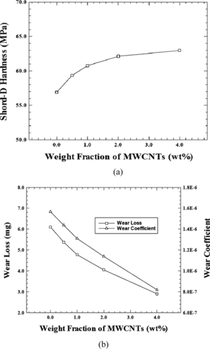
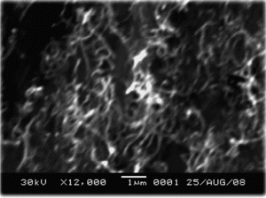
FIG. 6 (a) The variation of Shore-D hardness of MWCNTs/HDPE composites with varying the weight fraction of carbon nanotubes and (b) the variation of wear properties of MWCNTs/HDPE composite with varying the weight fraction of carbon nanotubes.
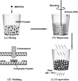
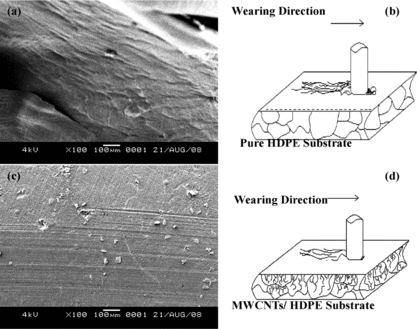
FIG. 7 (a) SEM images of worn surface of pure HDPE, (b) schematic figure indicating the worn surface of pure HDPE, (c) SEM images of worn surface of MWCNTs/HDPE composite and (d) schematic figure indicating the worn surface of MWCNTs/HDPE composite.

FIG. 7 (a) SEM images of worn surface of pure HDPE, (b) schematic figure indicating the worn surface of pure HDPE, (c) SEM images of worn surface of MWCNTs/HDPE composite and (d) schematic figure indicating the worn surface of MWCNTs/HDPE composite.

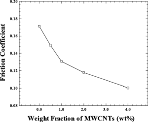
FIG. 8 Variation of friction coefficient of MWCNTs/HDPE composites with varying the weight fraction of carbon nanotubes.
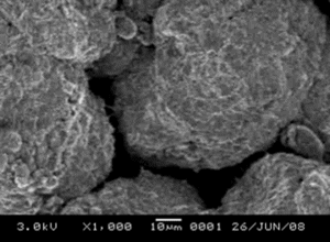
FIG. 8 Variation of friction coefficient of MWCNTs/HDPE composites with varying the weight fraction of carbon nanotubes.