26,956
Views
550
CrossRef citations to date
0
Altmetric
Review Article

Pharmaceutical Applications of Hot-Melt Extrusion: Part I

, , , , , , & show all
Pages 909-926 | Published online: 26 Sep 2008

Figures & data

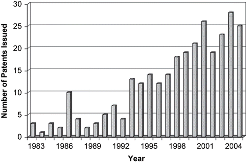
FIGURE 1. The number of hot-melt extrusion patents issued for pharmaceutical applications from 1983 to 2006.

FIGURE 1. The number of hot-melt extrusion patents issued for pharmaceutical applications from 1983 to 2006.

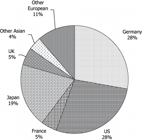
FIGURE 2. The number and percentage of hot-melt extrusion patents issued by country since 1983 for pharmaceutical applications.

FIGURE 2. The number and percentage of hot-melt extrusion patents issued by country since 1983 for pharmaceutical applications.

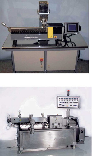
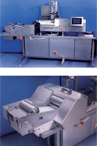
FIGURE 3. Twin screw prism USALAB digital 16 mm extruder (top), twin screw extruder (Courtesy of American Leistritz Co., Somerville, NJ) (bottom).

FIGURE 3. Twin screw prism USALAB digital 16 mm extruder (top), twin screw extruder (Courtesy of American Leistritz Co., Somerville, NJ) (bottom).

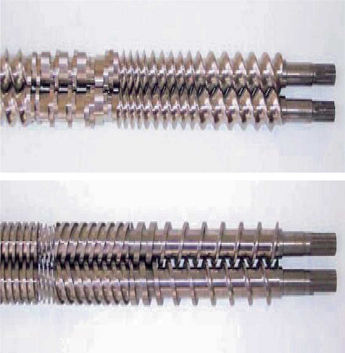
FIGURE 4. Twin screw design examples: intermeshing co-rotating twin-screw (top), and intermeshing counter-rotating twin-screw (Burns et al.). (Courtesy of American Leistritz Co., Somerville, NJ) (bottom).

FIGURE 4. Twin screw design examples: intermeshing co-rotating twin-screw (top), and intermeshing counter-rotating twin-screw (Burns et al.). (Courtesy of American Leistritz Co., Somerville, NJ) (bottom).

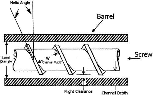
FIGURE 5. Diagram of an extruder screw (repka et al., 2002a). 1) the channel depth is the distance from the screw roots to the inner barrel surface; 2) the flight clearance is the distance between the screw flight and the inner barrel surface; 3) the channel width is the distance between two neighboring flights; 4) the helix angle is the angle between the flight and the direction perpendicular to the screw axis.

FIGURE 5. Diagram of an extruder screw (repka et al., 2002a). 1) the channel depth is the distance from the screw roots to the inner barrel surface; 2) the flight clearance is the distance between the screw flight and the inner barrel surface; 3) the channel width is the distance between two neighboring flights; 4) the helix angle is the angle between the flight and the direction perpendicular to the screw axis.

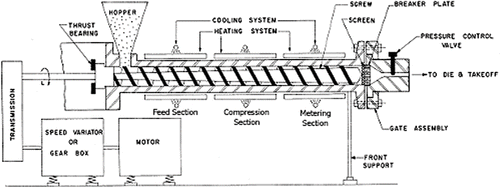
FIGURE 6. Schematic diagram of a single screw extruder.

FIGURE 6. Schematic diagram of a single screw extruder.

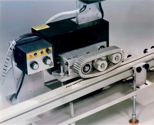
FIGURE 7. Illustration of a pelletizer used to chop rod shaped extrudates into pellets or granules. (Courtesy of Randcastle extrusion systems Inc., NJ).

FIGURE 7. Illustration of a pelletizer used to chop rod shaped extrudates into pellets or granules. (Courtesy of Randcastle extrusion systems Inc., NJ).

FIGURE 8. Illustration of a hot-melt extrusion film assembly (top) with chill roller flake unit (bottom). (Courtesy of Thermo Electron Corporation, MA).

FIGURE 8. Illustration of a hot-melt extrusion film assembly (top) with chill roller flake unit (bottom). (Courtesy of Thermo Electron Corporation, MA).

TABLE 1. Carriers Used to Prepare Hot-melt Extruded Dosage Forms

TABLE 2. Common Plasticizers Used in Pharmaceutical Dosage Forms

TABLE 3. Common Processing Aids Used in Hot-melt Extruded Dosage Forms

TABLE 4. Drug Substances Processed by Hot-melt Extrusion Techniques

TABLE 5. Common Methods Used for the Characterization of Hot-melt Extrudates
Reprints and Corporate Permissions

Please note: Selecting permissions does not provide access to the full text of the article, please see our help page How do I view content?

To request a reprint or corporate permissions for this article, please click on the relevant link below:

Academic Permissions

Please note: Selecting permissions does not provide access to the full text of the article, please see our help page How do I view content?

Obtain permissions instantly via Rightslink by clicking on the button below:

If you are unable to obtain permissions via Rightslink, please complete and submit this Permissions form. For more information, please visit our Permissions help page.