Figures & data
Figure 1. (A). Fennoscandian Ice Sheet, with selected Weichselian ice margin positions, interpreted distribution of cold-based ice during deglaciation, Baltic Ice Lake (Stroeven et al. Citation2016), boulder spreads (SGU data), fracture caves in disintegrated roches moutonnées (Sjöberg Citation1994). YD = Younger Dryas limit. (B). Map with locations and study areas, separated by feature type; boulder spread distribution. Some additional fracture caves reported by Sjöberg (Citation1994) also indicated. DTM after Aster GTOPO30. Figure © Svensk Kärnbränslehantering AB.
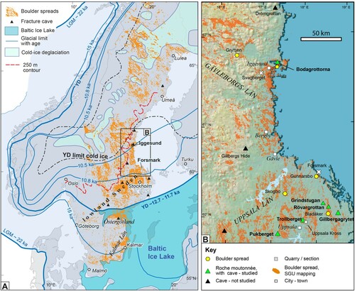
Figure 2. Rövargrottan: disrupted roche moutonnée with fracture cave. (A). Setting of Rövargrottan, shaded relief map, © Lantmäteriet. (B) Sketch map of disrupted roche moutonnée. Approximate outline of cave indicated. (C) North-south section; outlines constructed from stitched photo panorama. (D) Detail of gap between block A and block B. (E) Cave to east of block C, view to the north. Figure © Svensk Kärnbränslehantering AB.
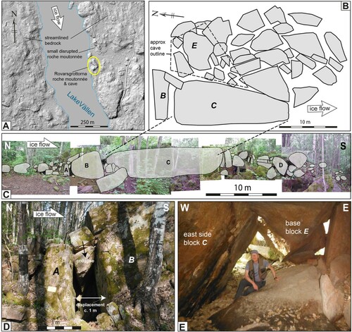
Figure 3. Gillbergagrytet: disrupted roche moutonnée with fracture cave. (A) Setting of Gillbergagrytet, shaded relief map © Lantmäteriet. (B) Orthophoto, © Lantmäteriet, with outline of blocks. (C) Map, based on orthophoto and field work. Height (in m) of selected blocks indicated; dip azimuth and dip of selected blocks shown. Approximate outline of cave indicated after Sjöberg (Citation1994). (D) WNW-ESE cross-section, with noted abraded surfaces shown. Line of section on (A). Some blocks are lettered for cross-referencing and mentioned in text. (E) Cave interior: fracture surfaces of blocks E and G match and show displacement of block E. (F) Oblique stoss-side of block E, with relative subsidence of block F. Figure © Svensk Kärnbränslehantering AB.
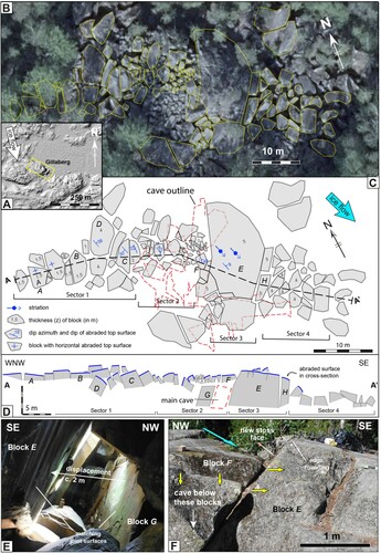
Figure 4. Bodagrottorna roche moutonnée. (A) Setting of Bodagrottorna roche moutonnée (centre), on hill-shaded relief map (© Lantmäteriet). Stippled areas mapped by SGU as boulder spreads. (B) Orthorectified air photo of Bodagrottorna roche moutonnée and immediate surroundings. Two linear boulder spreads extend in a SSE direction. Boreholes locations after Carlsten and Stråhle (Citation2000). (C) Digitised outlines of blocks on orthorectified airphoto (© Lantmäteriet). Numbers indicate block height (z, in m), measured in the field. Line of section for (D) is shown. Location of photos in are indicated. (D) Cross-section of the disrupted roche moutonnée. Approximate limit of disintegration at depth after Wänstedt (Citation2000). Figure © Svensk Kärnbränslehantering AB.
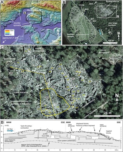
Figure 5. Bodagrottorna roche moutonnée. (A) Overview photo. In the foreground most surfaces are abraded (AS), in background is an exposed fracture plane (FS). (B) Slab-shaped block, with void in up-ice direction. Down-ice the block A has shunted beneath block B, by a form of back-thrusting. (C) Blocks with abraded tops showing vertical relative displacement (0.3–1 m), now presenting blunt stoss-sides (SS); view ∼ down-ice. Minor edge rounding. (D). Centre of roche moutonnée. Exposed fracture plane (FS), with displaced and toppled blocks on top. (E) Slab-shaped block with abraded top, resting on subhorizontal fracture plane (FS), with smaller boulders wedged beneath. Figure © Svensk Kärnbränslehantering AB.
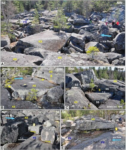
Figure 6. Bodagrottorna. (A) Fractures observed in boreholes (down hole video and radar) adjacent to Bodagrottorna, replotted from Carlsten and Stråhle (Citation2000). Depth versus fracture dip; open fractures highlighted. Clusters of steep fractures may record the same fracture, due to undulating fractures. (B) Histogram (bins 0.25 m) of block height near surface, measured in the field. All blocks have abraded tops, so this represents depth of first subhorizontal fracture beneath the abraded surface. Figure © Svensk Kärnbränslehantering AB.
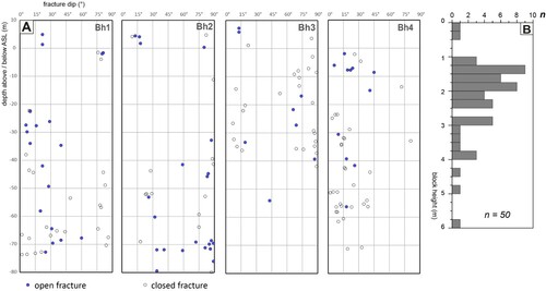
Figure 7. Field photos of selected disintegrated roche moutonnées. (A) Grindstugan: small partially disintegrated roche moutonnée; increasing disintegration down-ice. (B) Pukberget: rock tower with disrupted blocks in back ground. Basal fractures occur at different levels. Height of view c. 6 m. (C) Trollberget: Metre-sized blocks, in domino-style displacement. Top surfaces are abraded. (D) Trollberget: Metre sized block with blunt stoss side facing up-ice. Note minor edge rounding. Figure © Svensk Kärnbränslehantering AB.
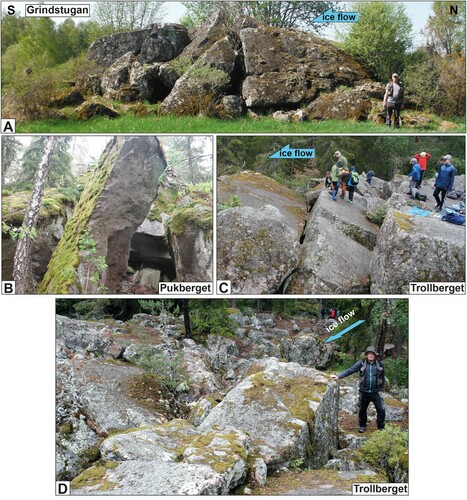
Figure 8. Comparison of block size in quarries and excavation sections, boulder spreads, and disrupted roche moutonnées (Bodagrottorna and Gillbergagrytet). Nominal B-axis is based on areal extent, used as proxy for boulder/block size. Boulders and blocks with B-axis < 0.8 m were not measured in boulder spreads and roche moutonnées. Figure © Svensk Kärnbränslehantering AB.
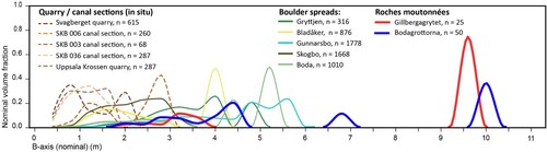
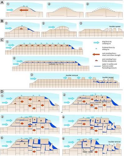
Figure 9. Conceptual models of glaciotectonic disintegration of roche moutonnées with different internal fracture patterns. Arrows indicate forces exerted by ice; and resisting forces of the rock mass. Arrow size indicates relative magnitude of forces. (A) Whaleback with few/no internal fractures. (B) Short roche moutonnée with continuous subhorizontal fractures. (C) Long roche moutonnée with continuous subhorizontal fractures, simple orthogonal fracture pattern. (D) Roche moutonnée with irregular, interlocking fracture pattern and discontinuous subhorizontal fractures. Figure © Svensk Kärnbränslehantering AB.