Figures & data
Figure 1. Digital elevation model of the Waterloo Moraine area showing the important landscape elements discussed in the text (after Chapman and Putnam Citation1984). The Waterloo Moraine is outlined by the thick red line and Waterloo Region by the dashed black and white line. The yellow arrows delineate the major corridors along which sediment was delivered into the moraine. asl: above sea level.
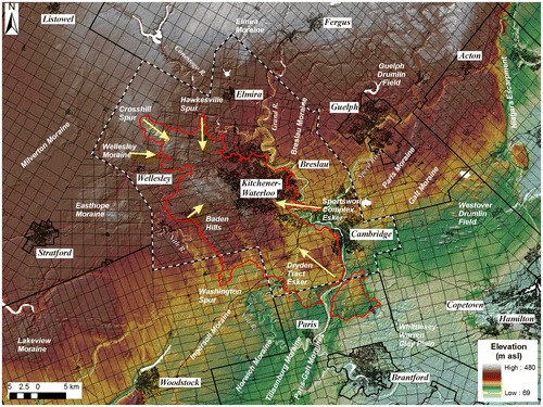
Table 1. Subsurface information used to create the three-dimensional (3D) hydrogeological model. WAGAIS: Waterloo Geotechnical Automated Information System; OGS: Ontario Geological Survey; University: Department of Earth Sciences, University of Waterloo; RMOW: Regional Municipality of Waterloo; MOE: Ministry of the Environment.
Figure 2. Idealized conceptual geological model for the Waterloo Moraine area. Aquifer units are shaded in dark grey, aquitards in white and bedrock in light grey.
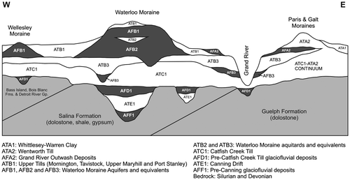
Table 2. Summary characteristics of the important hydrostratigraphic units modelled in the Waterloo Moraine area. OGS: Ontario Geological Survey. OGS hydrostratigraphic classes are defined in Figure 2.
Figure 3. Topography of the bedrock surface in the Waterloo Region. The red dashed line delineates the trunk axis of the Dundas/Wellesley buried bedrock valley. asl, above sea level.
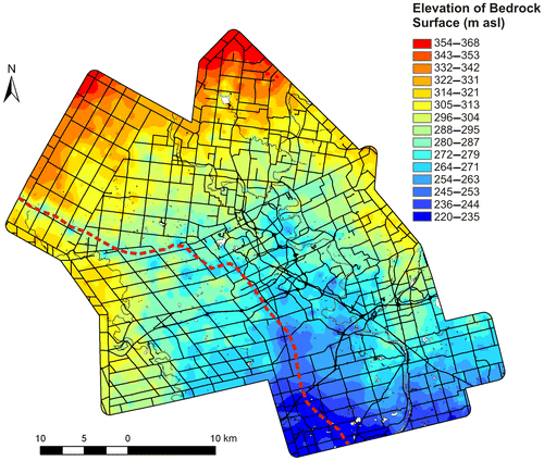
Figure 4. Thickness of Quaternary sediments within the Waterloo Region.
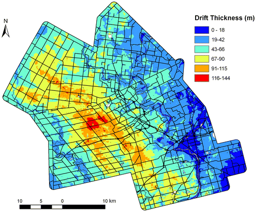
Figure 5. Two geologic cross-sections along transects transverse and parallel to the long axis of the Waterloo Moraine. The cross-sections were constructed using information from cored boreholes. Refer to Figure 2 and Table for keys to abbreviations of main lithologic units. OD refers to Older Drift and includes the sediments assigned to units ATE1, AFF1 and ATG1.
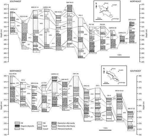
Figure 6. Isopachs of the major aquifer and aquitard units in the Waterloo Moraine area. White areas indicate locations where unit is not present.
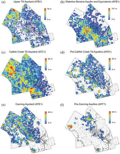
Figure 7. Photographs of sand and gravel units that are from the pre-Catfish Creek Till and Waterloo Moraine aquifers. (a) Open-framework cobble gravel with manganese oxide staining. (b) Isolated, discontinuous deposits of open-framework gravel (denoted by the arrows) within matrix-supported medium sand and gravel. (c) Contact between cobble gravel and silty Catfish Creek Till. (d) Stratigraphic architecture in the Waterloo Moraine which includes successions containing (i) gravel overlain by (ii) lacustrine mud, (iii) gravel, (iv) sand, and (v) silt. (e) Cobble gravel shown in Figure 6d with an open framework and basal medium sand matrix. (f) Bedded, well-sorted medium sand fining upwards to fine sand.
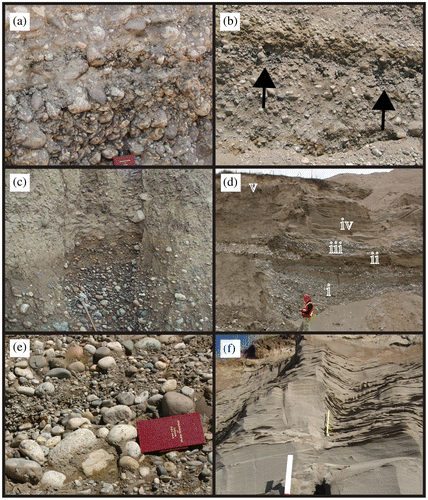
Figure 8. Subaquatic fan sediment facies model highlighting the proximal to distal hydraulic conductivity (in m/s) associated with distinct facies associations.
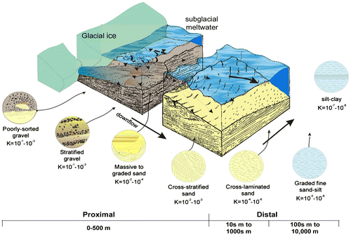
Figure 9. Overview of physical properties of lithostratigraphic units discussed in this study: (a) plot of grain-size data on Folk’s (Citation1954) ternary diagram, (b) cumulative curves of calcite/dolomite ratio and total carbonates and (c) plot of S- and P- wave vertical seismic velocities.
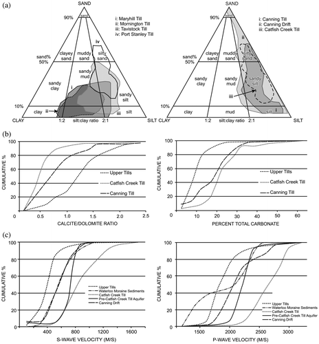
Figure 10. Graphical presentation of the sedimentary and geophysical logs of continuous core from borehole OGS-03-04, west-central Waterloo Moraine (from Bajc and Hunter Citation2006).
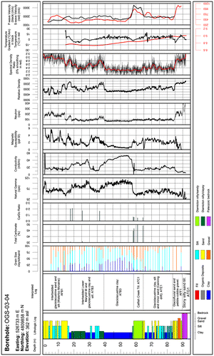
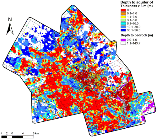
Figure 11. Depth to first aquifer of thickness greater than 3 m in the Waterloo Region. The areas in white are where aquifers of thickness greater than 3 m have not been modelled or where the depth to bedrock is greater than 1 m.