790
Views
3
CrossRef citations to date
0
Altmetric
Research Papers

Development and testing of a modified transparent velocity-head rod for stream discharge measurements

, &
Pages 372-384 | Received 27 Apr 2015, Accepted 01 Dec 2015, Published online: 26 Feb 2016

Figures & data

Figure 1. Modified transparent velocity-head rod (mTVHR). Images: Robin Pike.

Figure 1. Modified transparent velocity-head rod (mTVHR). Images: Robin Pike.

Table 1. Number of measurements taken using the mTVHR by each operator, by site and date.

Figure 2. (a) Measuring velocity-head using the modified transparent velocity-head rod (mTVHR). (b) Upstream water level as viewed through the mTVHR. Ruler in the background will slide down to meet the water level (or average if fluctuating) to define the upstream velocity-head level. Images: Emilia Young.

Figure 2. (a) Measuring velocity-head using the modified transparent velocity-head rod (mTVHR). (b) Upstream water level as viewed through the mTVHR. Ruler in the background will slide down to meet the water level (or average if fluctuating) to define the upstream velocity-head level. Images: Emilia Young.

Figure 3. Data points with Fonstad et al. (Citation2005) calibration (dashed) and modified transparent velocity-head rod (mTVHR) calibration (solid), where g = 9.8 m s–2 and h is the velocity-head measured on the mTVHR (m).
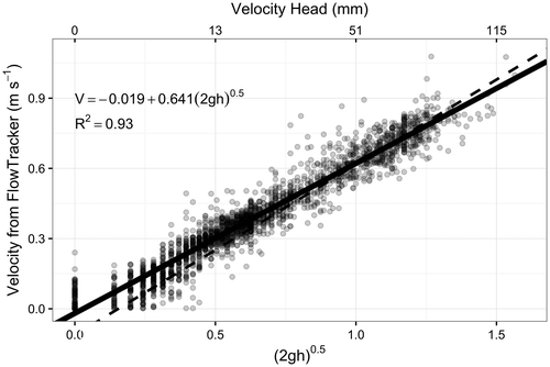

Figure 3. Data points with Fonstad et al. (Citation2005) calibration (dashed) and modified transparent velocity-head rod (mTVHR) calibration (solid), where g = 9.8 m s–2 and h is the velocity-head measured on the mTVHR (m).


Figure 4. Fitted lines by separate operators. There was strong evidence that the operators had different fits (p < 0.0001), but the effect of operator was small relative to residual variation. Note that Operator C only measured one stream with no measurements of a 0 mm velocity-head on the modified transparent velocity-head rod (mTVHR).
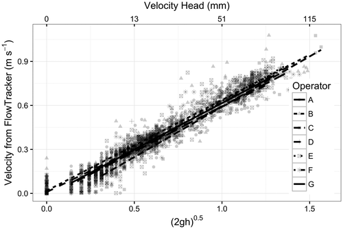
Figure 4. Fitted lines by separate operators. There was strong evidence that the operators had different fits (p < 0.0001), but the effect of operator was small relative to residual variation. Note that Operator C only measured one stream with no measurements of a 0 mm velocity-head on the modified transparent velocity-head rod (mTVHR).

Figure 5. Plots of the absolute difference in depth among operators measured using the modified transparent velocity-head rod (mTVHR) by (a) depth, (b) velocity, (c) calculated panel discharge and (d) site. The sites in plot (d) are 1 = Cowichan River Fish Fence; 2 = Cowichan River Smolt Fence; 3 = Cowichan River Department of Fisheries and Oceans (DFO) Side Channel; 4 = Cowichan River Trailer Park; 5 = Goldstream River; 6 = Muir Creek. The smoothed line in plots (a–c) is a loess curve. Points jittered to reduce superposition of points.
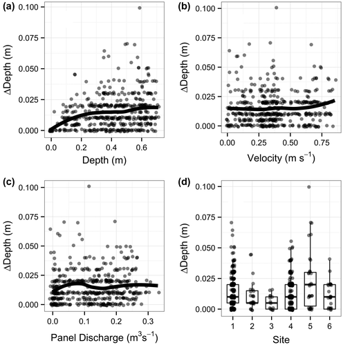

Figure 5. Plots of the absolute difference in depth among operators measured using the modified transparent velocity-head rod (mTVHR) by (a) depth, (b) velocity, (c) calculated panel discharge and (d) site. The sites in plot (d) are 1 = Cowichan River Fish Fence; 2 = Cowichan River Smolt Fence; 3 = Cowichan River Department of Fisheries and Oceans (DFO) Side Channel; 4 = Cowichan River Trailer Park; 5 = Goldstream River; 6 = Muir Creek. The smoothed line in plots (a–c) is a loess curve. Points jittered to reduce superposition of points.
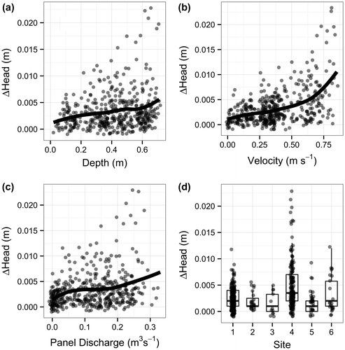

Figure 6. Plots of the absolute difference in velocity-head reading on the modified transparent velocity-head rod (mTVHR) among operators by (a) depth, (b) velocity, (c) calculated panel discharge and (d) site. The sites in plot (d) are 1 = Cowichan River Fish Fence; 2 = Cowichan River Smolt Fence; 3 = Cowichan River Department of Fisheries and Oceans (DFO) Side Channel; 4 = Cowichan River Trailer Park; 5 = Goldstream River; 6 = Muir Creek. The smoothed line in plots (a–c) is a loess curve. Points jittered to reduce superposition of points.


Figure 6. Plots of the absolute difference in velocity-head reading on the modified transparent velocity-head rod (mTVHR) among operators by (a) depth, (b) velocity, (c) calculated panel discharge and (d) site. The sites in plot (d) are 1 = Cowichan River Fish Fence; 2 = Cowichan River Smolt Fence; 3 = Cowichan River Department of Fisheries and Oceans (DFO) Side Channel; 4 = Cowichan River Trailer Park; 5 = Goldstream River; 6 = Muir Creek. The smoothed line in plots (a–c) is a loess curve. Points jittered to reduce superposition of points.


Figure 7. Differences in estimated velocity among operators measuring the same stream using the fitted relationship against the velocity as measured by the FlowTracker (FT). The X = Y line is shown on the plot. Points jittered to reduce superposition of points.
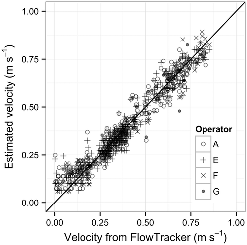

Figure 7. Differences in estimated velocity among operators measuring the same stream using the fitted relationship against the velocity as measured by the FlowTracker (FT). The X = Y line is shown on the plot. Points jittered to reduce superposition of points.


Figure 8. Estimated regression line between transformed modified transparent velocity-head rod (mTVHR) height and velocity as measured by FlowTracker (FT) (a) by depth class and (b) using a break point model. In both plots, the solid line is the fitted model using all of the data.
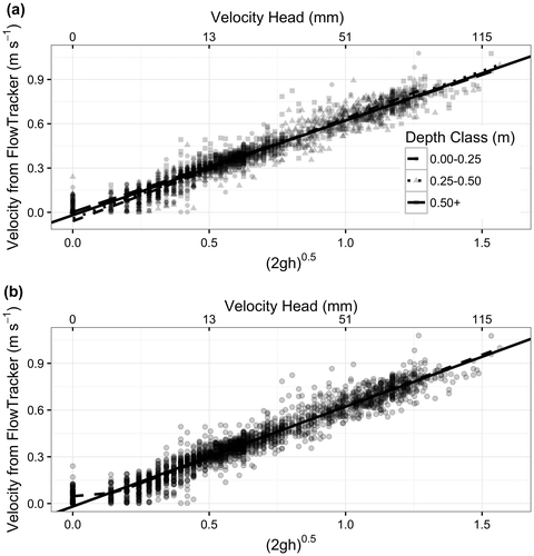

Figure 8. Estimated regression line between transformed modified transparent velocity-head rod (mTVHR) height and velocity as measured by FlowTracker (FT) (a) by depth class and (b) using a break point model. In both plots, the solid line is the fitted model using all of the data.


Figure 9. Comparison of estimated discharges from the new modified transparent velocity-head rod (mTVHR) and the Fonstad (2005) equation compared to those estimated using the FlowTracker (FT). The solid line is X = Y. RMSE = root mean square error between the predicted discharge using the equations and the discharge as estimated using the FT; RMSPE = root mean square percentage error between the predicted discharge using the equations and the discharge as estimated using the flow meters (FT/mTVHR).
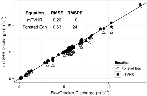

Figure 9. Comparison of estimated discharges from the new modified transparent velocity-head rod (mTVHR) and the Fonstad (2005) equation compared to those estimated using the FlowTracker (FT). The solid line is X = Y. RMSE = root mean square error between the predicted discharge using the equations and the discharge as estimated using the FT; RMSPE = root mean square percentage error between the predicted discharge using the equations and the discharge as estimated using the flow meters (FT/mTVHR).


Figure 10. Measuring fast velocities with the modified transparent velocity-head rod (mTVHR) at Carnation Creek: (a) bending of the mTVHR; (b) surging of velocity-head. Images: Gabe Sentlinger.
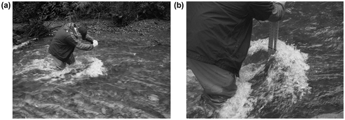

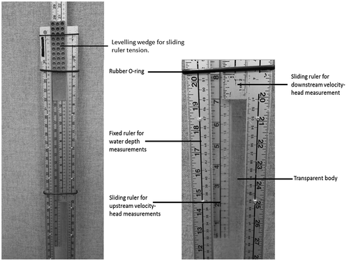
Figure 10. Measuring fast velocities with the modified transparent velocity-head rod (mTVHR) at Carnation Creek: (a) bending of the mTVHR; (b) surging of velocity-head. Images: Gabe Sentlinger.


Reprints and Corporate Permissions

Please note: Selecting permissions does not provide access to the full text of the article, please see our help page How do I view content?

To request a reprint or corporate permissions for this article, please click on the relevant link below:

Academic Permissions

Please note: Selecting permissions does not provide access to the full text of the article, please see our help page How do I view content?

Obtain permissions instantly via Rightslink by clicking on the button below:

If you are unable to obtain permissions via Rightslink, please complete and submit this Permissions form. For more information, please visit our Permissions help page.