Figures & data
Figure 1. Study area with the location of sampling sites. The number (n) of available samples is shown brackets in the legend. The limits of the study area correspond to those of previous studies from Cloutier et al. (Citation2013, Citation2015). The continental water divide between the St. Lawrence and the James Bay basins is also shown.
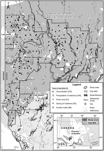
Figure 2. Regional hydrogeological conceptual model and water sampling scheme used to characterize the isotopic signature of all hydrological system components. (A) Fractured bedrock; (B) till; (C1) eskers and moraines; (C2) glaciofluvial sediments found between eskers and moraines, under the clay plain; (D) fine-grained deep-water glaciolacustrine sediments; (E) sublittoral sands and beach or eolian sediments; (F) organic deposits. The numbers (1 to 8) correspond to the sampled hydrological components and hydrogeological units, as identified in Table .
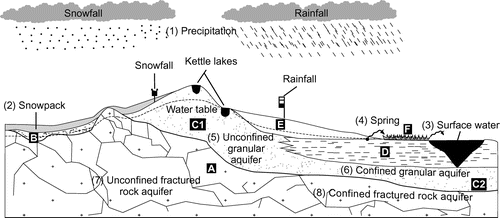
Table 1. Summarized characteristics of the regional hydrogeological framework. The numbers (1 to 8) of the sampled hydrological components and hydrogeological units correspond to those shown in Figures 2 and 8. The till (B) is not an aquitard, nor is it an aquifer in itself, although it can contribute to the flow of overlying or underlying aquifers.
Table 2. Summary of available water stable isotope data. The number of available samples and associated timeline are shown. As reported, most samples were collected during the summer period. Further details about the surface water samples are provided in Table .
Table 3. Summary of surface water sampling conditions. Most surface water samples were collected at a shallow depth below the surface, mainly during the summer period. Further details about the sampling procedures are provided in the text.
Table 4. Stability criteria for groundwater sample collection. Groundwater samples were collected only when the stability criteria were reached for three consecutive measurements separated by 5-minute intervals.
Figure 3. Isotopic composition of precipitation, surface waters, springs and groundwater. All data are shown in (a) whereas figure (b) provides a zoom on the surface and groundwater data. Average values are provided in figure (c). The flux-weighted average for precipitation is based on the three stations (Sainte-Hélène-de-Mancebourg, Amos, Bearn) where precipitation samples were collected between 2013 and 2015. The values correspond to the mean of the flux-weighted averages calculated for each station. The arithmetic average calculated for all precipitation samples is also shown. The error bars in (c) correspond to the standard deviation calculated for each sample series. The local meteoric water line (LMWL) and local evaporation line (LEL) derived from the data are also shown. Isotopic values are reported in permil units (‰) against the Vienna Standard Mean Ocean Water standard (VSMOW).
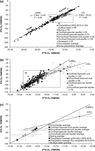
Figure 4. δ18O (a, b), 3H (c) and SEC (d) boxplots for precipitation, surface waters, springs and groundwater. Outlier data are excluded; the non-outlier range is defined as maximum and minimum values within 1.5 times the interquartile range. The available δ18O data are shown in (a) whereas a clearer view of surface and groundwater data is provided in (b). The classification reported in (c) is adapted from Clark and Fritz (Citation1997). UG: unconfined granular aquifers; UFR: unconfined fractured rock aquifers; CG: confined granular aquifers; CFR: confined fractured rock aquifers; SEC: specific electrical conductivity. In (a) and (d), the samples collected from the snowpack and at the precipitation monitoring stations are shown separately. δ18O values (a,b) are reported in permil units (‰) against the Vienna Standard Mean Ocean Water standard (VSMOW). δ18O values (a,b) are reported in permil units (‰) against VSMOW.
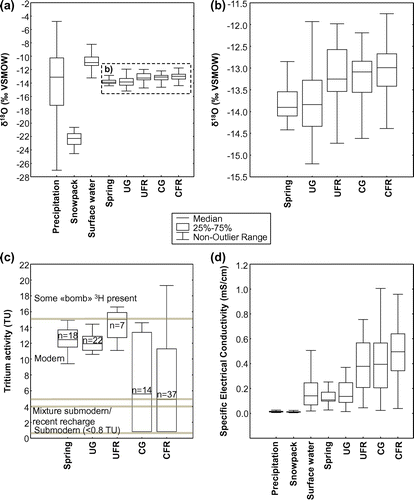
Figure 5. Seasonal variations in precipitation amounts and δ18O composition. See Figure 1 for the location of monitoring stations. The histogram showing precipitation amounts is based on data from July 2013 to July 2015 as recorded at the monitoring stations. Note: SHM: Sainte-Hélène-de-Mancebourg. δ18O values are reported in permil units (‰) against the Vienna Standard Mean Ocean Water standard (VSMOW).
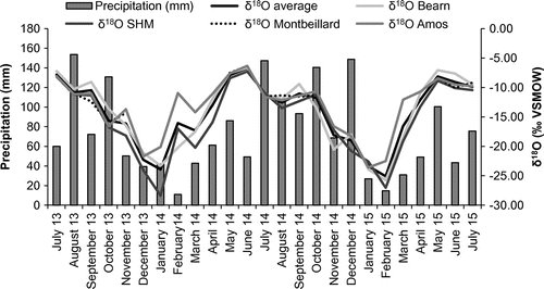
Table 5. Amount weighted average isotopic composition of precipitation at the four sampling stations (2013–2015).
Figure 6. Interpretation of the isotopic compositions of surface waters. Data in (a) represent the local evaporation line evaluated using the 99 available surface water samples. The Evaporation over Inflow (E/I) ratios are shown for points plotting on the Local Evaporation Line (LEL) at 0.5‰ intervals along the x-axis. These E/I ratios are shown for three scenarios (see text for details). Further details with respect to the types of surface water samples are provided in (b) and in Table . Isotopic values are reported in permil units (‰) against the Vienna Standard Mean Ocean Water standard (VSMOW).
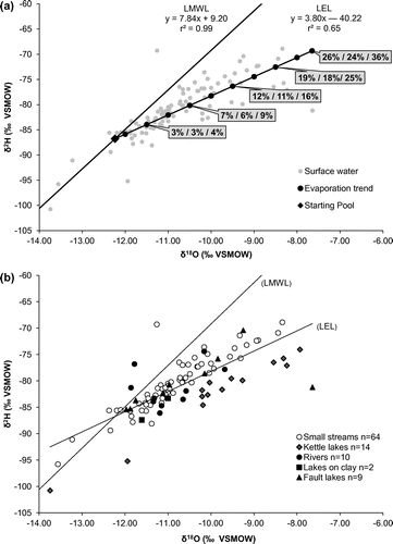
Figure 7. Specific electrical conductivity (SEC) vs δ18O of springs, surface waters and groundwater. Three end-members are shown: (A) corresponds to groundwater recharged during snowmelt, (B) corresponds to groundwater that is less impacted by snowmelt-induced recharge and (C) corresponds to geochemically evolved groundwater found farther along regional flowpaths. See text for further details. The six main outliers (as described in the text) are not shown in this figure. Figure (a) shows the distribution of data whereas the corresponding averages are shown in (b). δ18O values are reported in permil units (‰) against the Vienna Standard Mean Ocean Water standard (VSMOW).
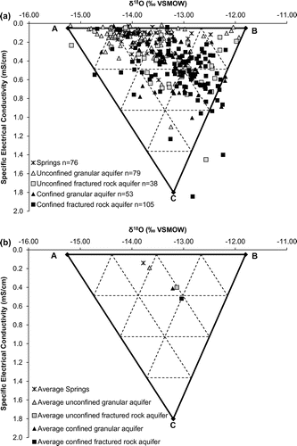
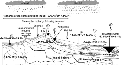
Figure 8. Isotopic variations within local, intermediate and regional flow systems. The range of measured isotopic compositions is shown for the sampled hydrological components and hydrogeological units, as identified in Tables and . Areas of preferential snowmelt-induced recharge are identified. Flowpaths at various scales are shown. (R) Recharge area; (E) evaporation; (T) transpiration; (GW/SW) groundwater/surface water interactions (herein mainly groundwater exfiltration). The numbers (1 to 8) correspond to the sampled hydrological components and hydrogeological units, as identified in Table .