Figures & data
Fig. 1 Bathymetry (metres) of Great Bear Lake in the model domain and temperature moorings (solid red circles), APEX profiling buoys (solid green circles) and meteorological stations (solid blue squares).
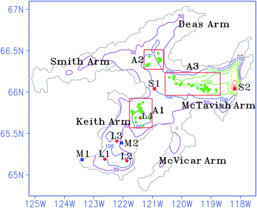
Fig. 2 A comparison of time series of 3-hourly atmospheric variables averaged at stations M1 and M2 and GEM forecasted variables for August to September 2008.
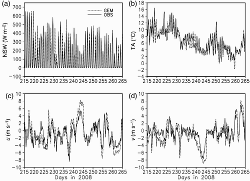
Fig. 3 The spatial distribution of 10 m wind vector, latent heat flux (LHF), sensible heat flux (SHF), at the surface produced by GEM on 31 August (left panels) and 3 September (right panels) 2008.
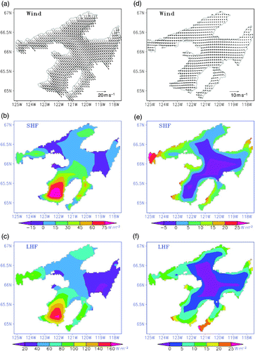
Table 1. Summary of model sensitivity experiments.
Fig. 4 Near-surface temperature averaged over August and September 2008 from AVHRR data and the CTRL run, respectively.
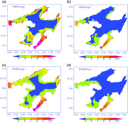
Fig. 5 Time-depth distributions of the modelled and observed temperatures at moorings L1, L2, L3 and L4, respectively.
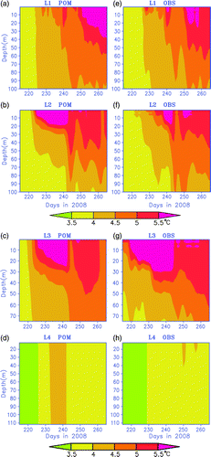
Fig. 6 Time-depth distributions of the grid-averaged modelled and observed temperatures at A1, A2 and A3, respectively.
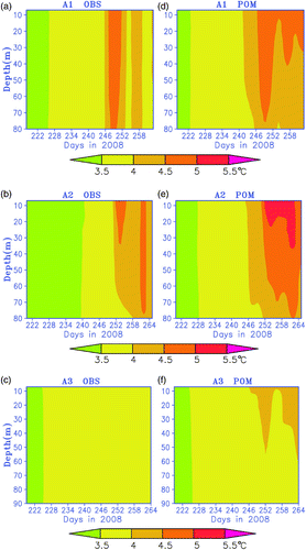
Fig. 7 The vertical distributions of RMSE between modelled and observed temperatures at the three temperature moorings (L1, L2 and L3) and the grids around the APEX profilers (A1, A2 and A3).
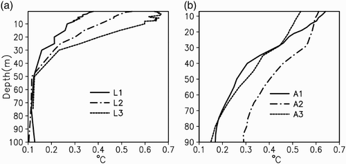
Fig. 8 Cross-section of the modelled water temperature from the CTRL run on 31 August 2008 (a) along 66.3°N and (b) along 122°W.
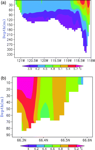
Fig. 9 The seasonal mean (averaged over August to September 2008) of depth-averaged currents.
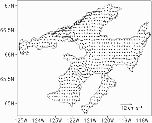
Fig. 10 Time series of the vertical distribution of temperature differences between sensitivity experiments and the CTRL runs.
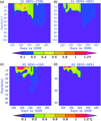
Fig. 11 The seasonal mean of depth-averaged currents averaged over August to September 2008 for various sensitivity runs described in .
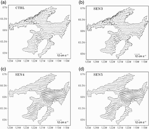
Fig. 12 The spatial distributions of the difference in (a) lake surface temperature and (b) surface net heat flux between SR and BR experiments.
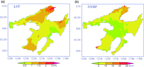
Fig. 13 The spatial distributions of the differences in the components of the heat fluxes between SR and BR experiments averaged over the entire simulation period.
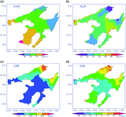
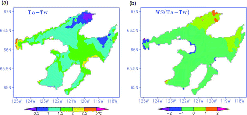
Fig. 14 The spatial distributions of the differences between the SR and BR experiments averaged over the entire simulation period for (a) air-water temperature and (b) the product of wind speed and the temperature gradient.