Figures & data
Table 1. Subject information.
Figure 1. Twenty-two sequential measurement pathways. RFH: right forehead, LFH: left forehead, RH: right hand, RF: right foot, LH: left hand and LF: left foot. For example, RH-RF means: pathway from the right hand to the right foot.
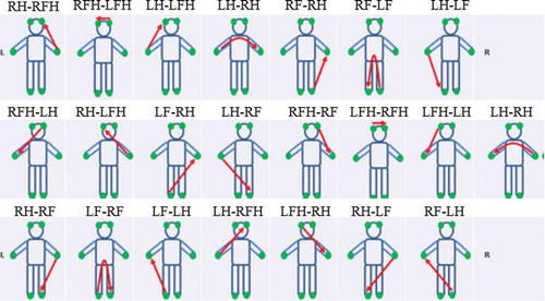
Figure 2. Measurement pathways of BIA method. The sequence of measurements proceeds as follows. For the right arm resistance (RRA), AC was applied between E1 and E5 and recorded voltage between E2 and E4. The recorded voltage between E4 and E8 was used to obtain the trunk resistance (RT) and recorded voltage between E6 and E8 was used to obtain the right leg resistance (RRL). The AC was applied between E3 and E7 and recorded voltage between E2 and E4 was used to obtain the left arm resistance (RLA). Lastly, recorded voltage between E6 and E8 was used to obtain the left leg resistance (RLL) (Malavolti et al. Citation2003).
Figure 3. Sample linear representations of the “Na” value versus Height1.
Table 2. Chronobiometric parameters for the EDA data (voltage).
Figure 4. The cosinorgram of the RH-LF EIS data. The vertical dotted lines indicate the folding at 360°. The circadian rhythm and standard error bands were estimated from the single cosinor procedure. The circles and lines indicate the least squared mean and standard error at each circadian hour.
Table 3. Chronobiometric parameters for the BIA data.
Figure 5. Sample BIA data (resistance, reactance and phase angle for the right arm, trunk and right leg at 50 kHz and leg reactance at 250 kHz). Each dot and line represent the mean and standard deviation, respectively.