Figures & data
Figure 1. MicroCT analysis of salt-leached, photopolymerized scaffold fabricated with Kerr dental lamp. The material was methacrylate end-capped poly(D,L-lactide), and camphorquinone has been used as photoinitiator.
Figure 2. Pore size distribution of the photopolymerized scaffold visualized by microCT.
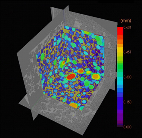
Figure 3. Schematic representation of the stereolithography (SLA) system. An ultraviolet (UV) laser is used to solidify the model's cross-section while leaving the remaining areas in liquid form. The movable table then drops by a sufficient amount to cover the solid polymer with another layer of liquid resin.
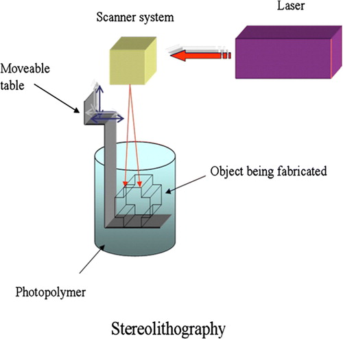
Figure 4. Example of a scaffold fabricated using stereolithography (SLA). A: Computer-aided design (CAD) image of the structure. B: Completed SLA-fabricated scaffold with very regular pore size distribution. C: Microcomputerized tomography (microCT) image of the scaffold.
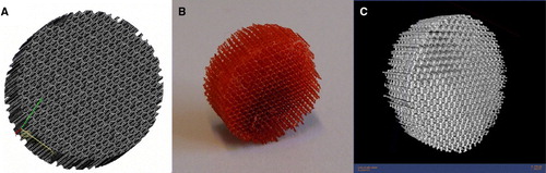
Figure 5. Scheme of 3D printing process. A stream of adhesive droplets is expelled through an inkjet printhead, selectively bonding a thin layer of powder particles to form a solid shape.
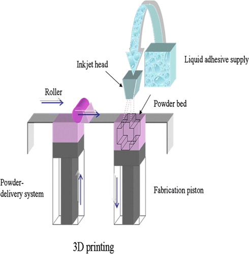
Figure 6. Scheme of selective laser sintering (SLS) technique. The laser selectively fuses powdered material by scanning cross-sections generated from a 3D digital description of the part on the surface of a powder bed. After each cross-section is scanned, the powder bed is lowered by one layer thickness, a new layer of material is applied on top, and the process is repeated until the part is completed.
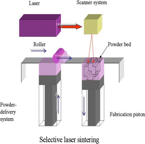
Figure 7. Scheme of the fused deposition modeling (FDM) system. FDM uses a moving nozzle to extrude a fiber of polymeric material from which the physical model is built layer by layer.
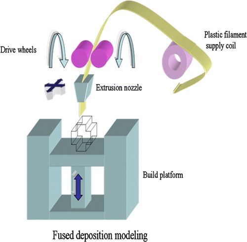
Figure 8. Sketch of the 3D Bioplotter® system. The material is plotted through the nozzle into a liquid medium with matching density. The material solidifies when it comes in contact with the medium. The liquid medium compensates for gravity, and hence no support structure is needed.
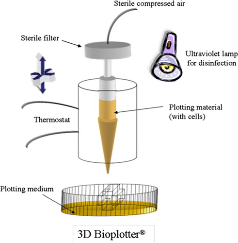
Figure 9. The principle of the two-photon polymerization process. Overlap of photons from the ultrashort laser pulse leads to chemical reactions between monomers and starter molecules within the transparent matrix.
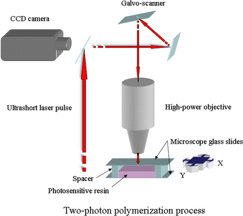
Table I. Comparison of different rapid prototyping (RP) methods on the basis of their achievable resolution, advantages, and disadvantages.