Figures & data
Figure 1 Distribution of 65 new geodetic sites in southern Queensland and locations of three nearby GNSS CORS sites at Mitchell, Eidsvold and Toowoomba. Also plotted are land parcels designated as petroleum leases for production and exploration permits for petroleum, coal seam gas (CSG) wells and other petroleum wells (these data obtained on 11 December 2014 from the Queensland State Department of Natural Resources and Mines’ ‘Queensland Globe’ service). Background grey shading indicates the spatial extent of the Surat Basin.
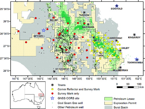
Figure 2 (a) Engineering drawing of the soil-profile survey mark design. Dimensions in millimetres. (b) Installed soil profile survey mark at Site 8 with valve box lid removed.
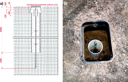
Figure 3 (a) Engineering drawing of bedrock survey mark design. Dimensions in millimetres. (b) Installed bedrock survey mark at Site 30 with attached instrument holder and GNSS antenna during a survey (the pink length of rod is an additional component of the particular GNSS antenna model used here).
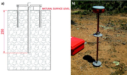
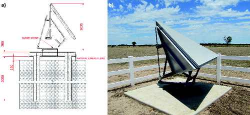
Figure 4 (a) Engineering drawing of the 1.5 m triangular trihedral corner reflector (side-on view) and concrete slab design for construction in the soil profile. Dimensions in millimetres. (b) 1.5 m corner reflector installed at Site 26. Concrete slab dimension is 2 m square.