
Figures & data
Figure 1. Scientometric analysis: topological indices based on degree, across different nations.
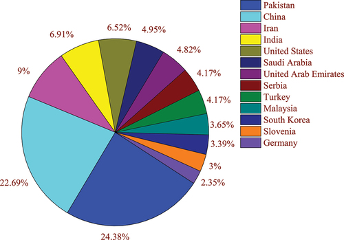
Figure 2. Scientometric analysis: keywords for topological indices based on degree.
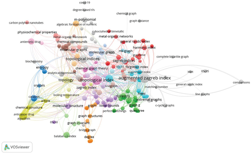
Figure 3. (a) Unit structure of copper(II) fluoride and (b) crystal sheet of copper(II) fluoride
.
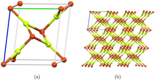
Table 1. Edge partition of .
Figure 4. Graphical depiction of ,
,
, and
.
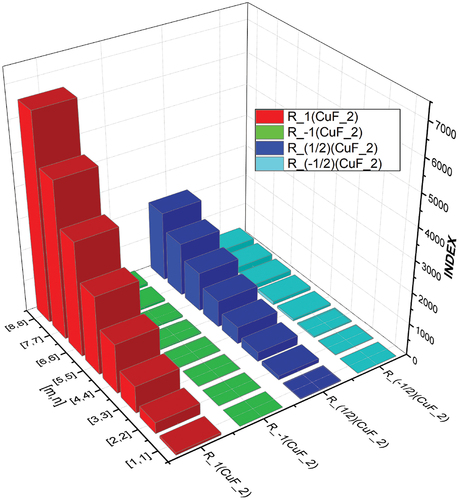
Table 2. Numerical comparative analysis for ,
,
, and
.
Figure 5. Graphical depiction of ,
,
, and
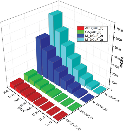
Table 3. Numerical comparative analysis of ,
,
, and
.
Figure 6. Graphical depiction of ,
, and
.
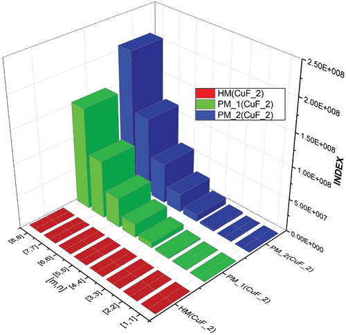
Table 4. Numerical comparative analysis of ,
and
.
Figure 7. Graphical depiction of ,
, and
.
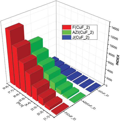
Table 5. Numerical comparative analysis of ,
, and
.
Figure 8. Graphical depiction of and
.
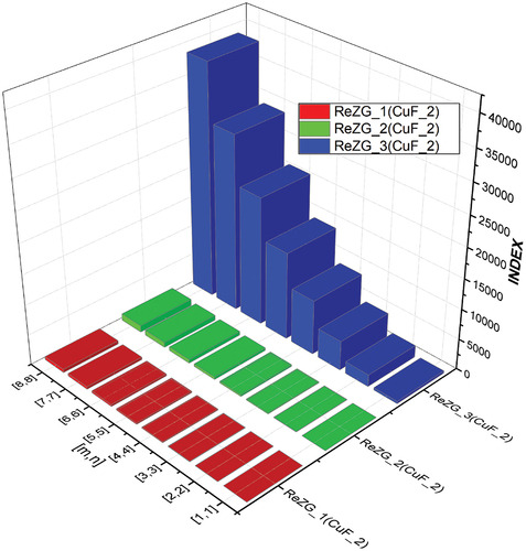
Table 6. Numerical comparative analysis of ,
, and
.
Figure 9. (a) between
and
and (b)
between
and
.
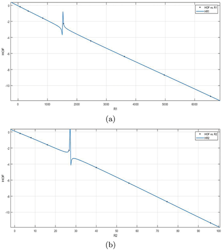
Figure 10. (a) between
and
and (b)
between
and
.
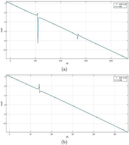
Figure 11. (a) between
and
and (b)
between
and
.
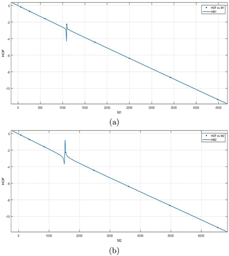
Figure 12. (a) between
and
and (b)
between
and
.
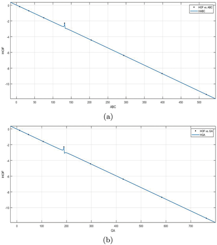
Figure 13. between
and
.
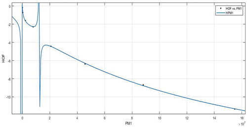
Figure 14. (a) between
and
and (b)
between
and
.
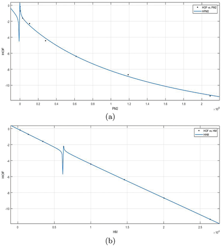
Figure 15. (a) between
of
and (b)
between
of
.
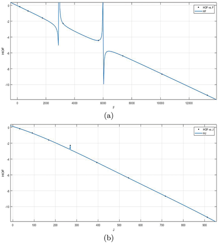
Figure 16. (a) between
and
and (b)
between
and
.
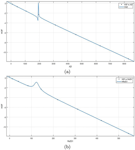
Figure 17. (a) between
and
and (b)
between
and
.
uaai_a_2327235_sm9635.jpg
Download JPEG Image (190.8 KB)
Data Availability Statement
Data sharing is not applicable to this article as no new data were created or analyzed in this study.