1,786
Views
27
CrossRef citations to date
0
Altmetric
Original Articles

Protein adsorption mechanisms on solid surfaces: lysozyme-on-mica

&
Pages 561-566 | Received 29 Oct 2008, Accepted 08 Nov 2008, Published online: 20 Apr 2009

Figures & data

Figure 1 Coverage of the substrate observed in AFM experiments against exposure time. The smooth curves come from a solution of the diffusion equation, assuming translational symmetry across the system, starting with a uniform distribution of the lysozyme in solution and a bare adsorbing substrate. The sticking coefficient onto bare substrate is P = 1.0 and 0.01.
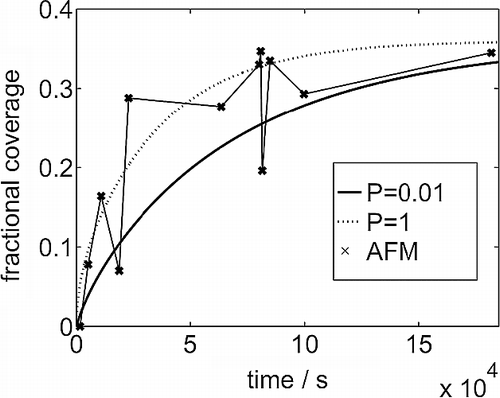
Figure 1 Coverage of the substrate observed in AFM experiments against exposure time. The smooth curves come from a solution of the diffusion equation, assuming translational symmetry across the system, starting with a uniform distribution of the lysozyme in solution and a bare adsorbing substrate. The sticking coefficient onto bare substrate is P = 1.0 and 0.01.

Figure 2 Cluster size distributions at time 180,000 s. The abscissa is scaled to the mean size. The bars are from the AFM experiments and the lines from the simulations with mobile clusters.
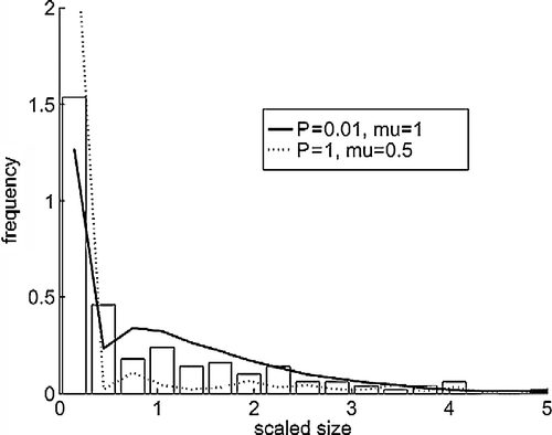
Figure 2 Cluster size distributions at time 180,000 s. The abscissa is scaled to the mean size. The bars are from the AFM experiments and the lines from the simulations with mobile clusters.

Figure 3 Cluster density (number per 3 × 3 nm area) evolution over time from AFM images and the simulation models.
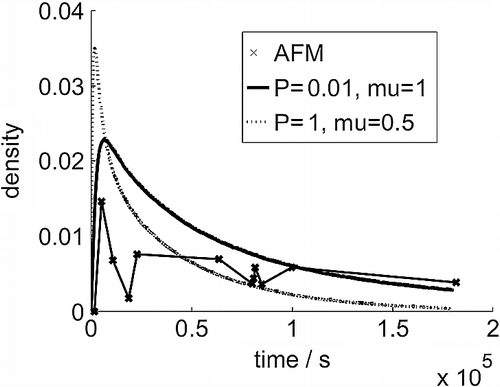
Figure 3 Cluster density (number per 3 × 3 nm area) evolution over time from AFM images and the simulation models.

Figure 4 Surface charge plot of the isolated lysozyme in solution. Dark indicates positive charge, and grey negative. The protein has a net positive charge of +4e at pH 7.
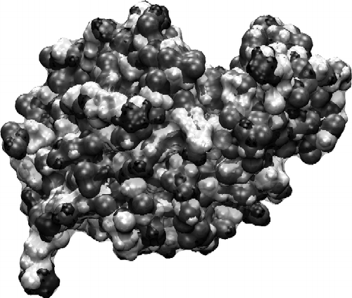
Figure 4 Surface charge plot of the isolated lysozyme in solution. Dark indicates positive charge, and grey negative. The protein has a net positive charge of +4e at pH 7.

Figure 5 MD simulation of lysozyme in orientation 1 above the surface. The left image is the initial configuration after thermalisation, and the right is after 20 ns at 300 K.
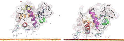
Figure 5 MD simulation of lysozyme in orientation 1 above the surface. The left image is the initial configuration after thermalisation, and the right is after 20 ns at 300 K.
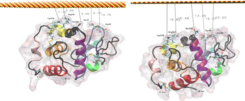
Table 1. Initial and final distances between the plane of the surface and the key residues involved in the early stages of lysozyme adsorption in orientation 1 (see Figure ).

Figure 6 MD simulation of lysozyme in orientation 2 above the surface. The left image is the initial configuration after thermalisation, and the right is after 20 ns at 300 K.

Figure 6 MD simulation of lysozyme in orientation 2 above the surface. The left image is the initial configuration after thermalisation, and the right is after 20 ns at 300 K.

Table 2. Initial and final distances between ‘uppermost’ residues in orientation 2 (Figure ) and the plane of the surface.