Figures & data
Figure 1. Sketches of LH system objective arrangements: (a) common laboratory geometry of apochromat objective for optical observation and on-axis laser focus, focal distance typically about 30 mm. (b) Common synchrotron geometry of apochromat objective combined with a 45 tilted mirror (TM), focal distance typically about 60 mm. (c) Perforated parabolic mirror for use both in laboratory and synchrotron, reflective focal distance here 33 mm. (d) Reflective objective combined with 45
tilted mirror, focal distance typically well above 70 mm.
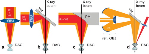
Figure 2. Sketch of the essential aspects of the LH system that allowed for direct comparison of the PM to an apochromat (APO) of ca. 30 mm focal length. To achieve that, we modified the versatile portable LH system designed for at synchrotron [Citation12]. Optical paths are shown in orange, laser path in red, lens objectives in green and the two dichroic mirrors in purple. All fully reflective mirrors, one laser beamsplitter and one halfmirror in front of the mirror with pinholes are shown in light blue. The motorized slim diode to record the X-ray transmission profiles (in ) are shown in darker blue. The angle of the normal of the mirror at the spectrometer entrance with respect to the optical path is 17.
![Figure 2. Sketch of the essential aspects of the LH system that allowed for direct comparison of the PM to an apochromat (APO) of ca. 30 mm focal length. To achieve that, we modified the versatile portable LH system designed for at synchrotron [Citation12]. Optical paths are shown in orange, laser path in red, lens objectives in green and the two dichroic mirrors in purple. All fully reflective mirrors, one laser beamsplitter and one halfmirror in front of the mirror with pinholes are shown in light blue. The motorized slim diode to record the X-ray transmission profiles (in Figure 6) are shown in darker blue. The angle of the normal of the mirror at the spectrometer entrance with respect to the optical path is 17∘.](/cms/asset/58bbaad7-9b25-4685-b7de-dfda0e3554f2/ghpr_a_1921173_f0002_oc.jpg)
Figure 6. (a) Transmission scan of a DAC in the LH system equipped with a DAC with Fe-containing sample, recorded with the slim removable diode shown in at beamline P01, PETRA III. The X-ray focus was m
FWHM. One scan shows the transmission profile of the PM without DAC (red line), one scan shows the transmission profile of DAC downstream of the PM, ready for laser heating. Due to the attenuation by approximately 4 mm of diamond in the DAC, the curves were recorded with different gain of the diode and then scaled. Note that the scans are the result of a convolution of the dimensions of DAC gasket hole and PM perforation hole with the dimensions of the X-ray beam. (b) Sketch illustrating the perforation of the PM. (c) Photograph of the hole at the mirror surface.
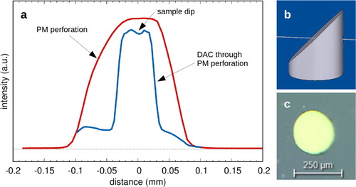
Figure 3. Photographs of a sample in the DAC (a–c) and a sample carrier grid (d–f), recorded with a Leica M205 binocular (a,d), and in the LH system with the PM (b,e) and with the apochromatic objective (c,f). (a–c) A triangular piece of Pt foil (ca. m
) in NaCl in a DAC, before pressurization. The sample chamber is approximately 130 μm in diameter, see scale bar in (a). (d–f) A transmission electron microscope sample carrier grid of 100 μm periodicity. Arrows in (e,f) are for orientation and indicate the same object.
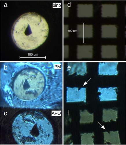
Figure 4. Laser focus profiles without and with beam shaping (blue and red lines, respectively). The unshaped peak has been downscaled to enable comparison of the two beam shapes. Dashed lines represent Gaussian fits from which we derived FWHM values. Inset photo: Heating of a platinum foil in a DAC at 20 GPa with the PM without beam shaping. The black dot in the center of the hot spot is the pinhole entrance to the spectrometer for temperature measurement.
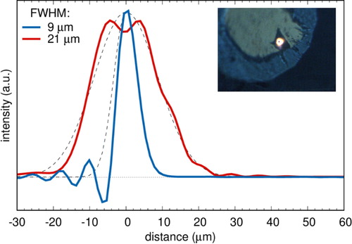
Figure 5. Comparison of radiospectrometric temperature determination with the parabolic mirror (left column of figures) and the apochromatic objective (right column), and the influence of spectral distortion due to chromatic aberration on temperature determination. (a,d): Spectrum, Planck fit and resulting temperature estimate. (b,e): Relative difference of spectrum and fit, the difference is area-shaded for illustration. (c,f): Plot of two-color temperature (spacing of 100 nm). Dashed lines represent temperature determined from Planck fit.
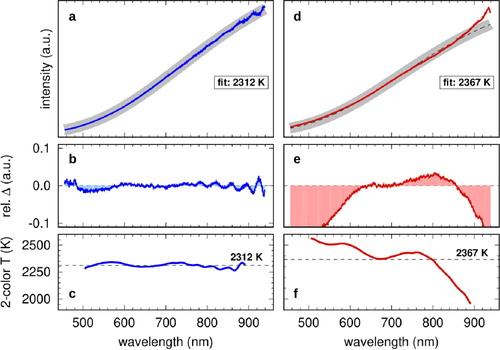
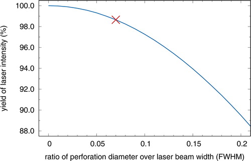
Figure 7. The minimum yield of laser light reflected from a perforated PM as a function of the ratio of perforation diameter over FWHM of the laser beam. The cross at a ratio of 0.07 with a laser yield of 98.6% indicates a minimum estimate for the here reported setup. See text for details.