Figures & data
Figure 1 Relative permittivity of gain-impregnated SiO2 with Γ = 10−3 ω0 and ω0 = (2π) 600 × 1012.
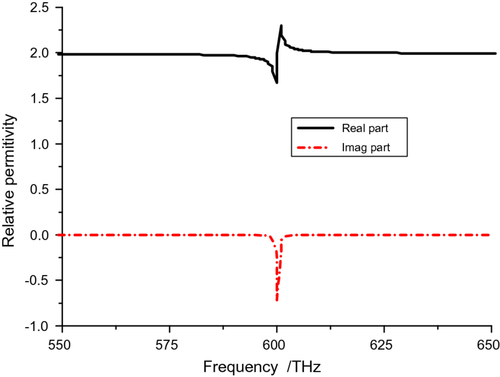
Figure 2 Plane wave excited C-CNP model. The incident plane wave source has the wave vector (kx = 1, ky = 0, kz = 0). (a) CNP model and its parameters; (b) plane wave incident on the cylinder from different directions α and β; (c) Ez polarization, electric field vector along the (x = 0, y = 0, z = 1) direction and α = β = 0°; (d) Ey polarization, electric field vector along the (x = 0, y = 1, z = 0) direction and α = β = 0°; (e) Et polarization, electric field vector along the (x = 0, y = 0, z = 1) direction and α = 90°, β = 0°.
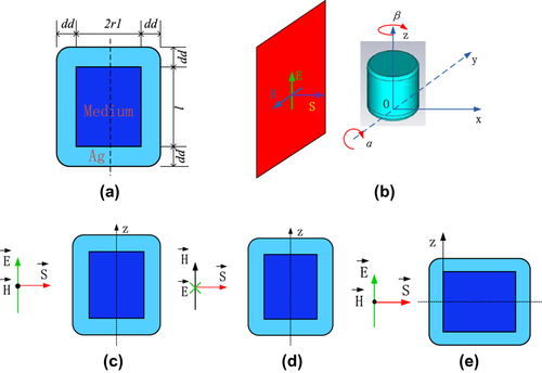
Figure 3 Ey polarization results for C-CNP with l = 31.5 nm, dd = 6 nm, and its core radius swept from 22 to 23 nm. (a) Scattering, and (b) ACSs.
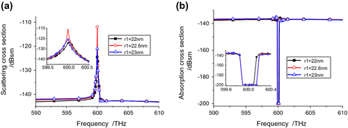
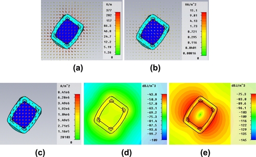
Figure 4 Field distributions for the Ey polarization case in the xoy-cut and zox-cut planes at f = 600 THz. (a) Electric field in the zox-cut plane; (b) magnetic field in the xoy-cut plane; (c) current density in the zox-cut plane; power flow in the (d) xoy-cut and (e) zox-cut planes; electric field energy density in the (f) xoy-cut and (g) zox-cut planes; and magnetic field energy density in the (h) xoy-cut and (i) zox-cut planes.
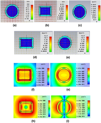
Figure 5 Et polarization results for C-CNP with l = 31.5 nm, dd = 6 nm, and its core radius swept from 22 to23 nm. (a) RCS, and (b) ACS.
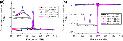
Figure 6 Predicted distributions for the Et polarization case of the (a) electric field, (b) power flow, (c) current density, (d) electric and (e) magnetic field energy densities and (f) far field, 3D gain pattern for the optimized, active C-CNP with α = 90°, β = 0° at f = 600THz.
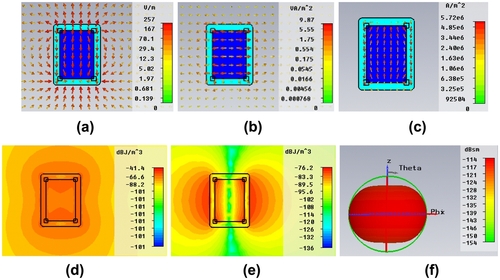
Figure 7 Comparison of the (a) scattering and (b) ACSs for the three basic polarization cases.
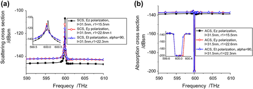
Figure 8 Cross-sections when α is swept with β = 0°. (a) SCS, and (b) ACS values vs. frequency.
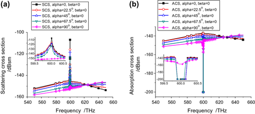
Figure 9 Cross sections obtained with α = 45° and by sweeping the angle β. (a) SCS, and (b) ACS values vs. frequency.
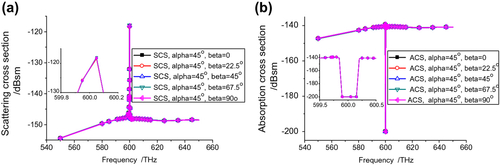
Figure 10 Cross sections obtained with α = 90°, and by sweeping the angle β. (a) SCS, and (b) ACS values vs. frequency.
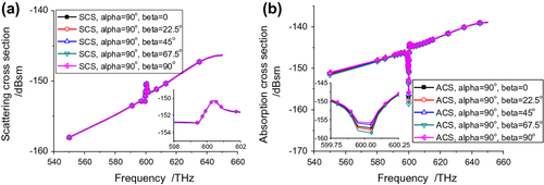
Figure 11 Distributions for α = 22.5° and β = 0°, at the resonance frequency 600.05 THz for the vertical polarized incident plane wave. (a) Electric field; (b) power flow; (c) current density; and (d) electric and (e) magnetic field energy density.
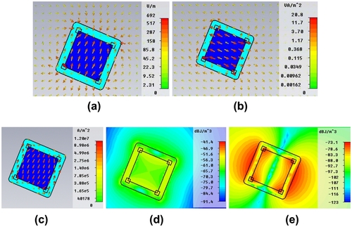
Figure 12 Distributions at the resonance frequency 600.05 THz for the vertically polarized incident plane wave incident on the active C-CNP with α = 45° and β = 45°. (a) Electric field; (b) power flow; (c) current density; and (d) electric and (e) magnetic field energy density.