910
Views
0
CrossRef citations to date
0
Altmetric
Articles

Width estimation of a subsurface water-filled crack using internal multiple reflections from electromagnetic scattering model of a cylinder

, , &
Pages 1034-1048 | Received 02 Jan 2017, Accepted 09 Apr 2017, Published online: 16 May 2017

Figures & data

Figure 1. (a) A dielectric cylinder impinged by a plane wave. (b) Illustration of ray path for a dielectric cylinder impinged by a plane wave. (c) Propagation processes of internal multiple reflections.
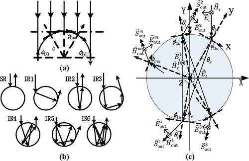
Figure 1. (a) A dielectric cylinder impinged by a plane wave. (b) Illustration of ray path for a dielectric cylinder impinged by a plane wave. (c) Propagation processes of internal multiple reflections.

Figure 2. (a) Ratio of path length to the diameter (L/d) with respect to incident angles. (b) (L/d) with respect to relative permittivities. (c) (t/τ) with respect to incident angles. (d) (t/τ) with respect to relative permittivities.
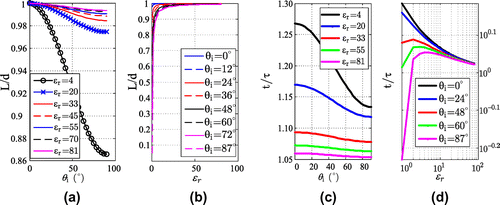
Figure 2. (a) Ratio of path length to the diameter (L/d) with respect to incident angles. (b) (L/d) with respect to relative permittivities. (c) (t/τ) with respect to incident angles. (d) (t/τ) with respect to relative permittivities.

Figure 3. Backscattering field of a cylinder with and .

Figure 3. Backscattering field of a cylinder with and .

Table 1. Theoretic and simulated values of normalized time delay.

Figure 4. (a) The SPWV distribution of the electric field from cylinder with d = 4 cm and . (b) From the cylinder with d = 4 cm, . (c) From the cylinder with d = 4 cm, . (d) From the cylinder with d = 4 cm, .

Figure 4. (a) The SPWV distribution of the electric field from cylinder with d = 4 cm and . (b) From the cylinder with d = 4 cm, . (c) From the cylinder with d = 4 cm, . (d) From the cylinder with d = 4 cm, .

Figure 5. (a) The SPWV distribution of the electric field from cylinder with d = 8 cm and . (b) From the cylinder with d = 8 cm, . (c) From the cylinder with d = 8 cm, . (d) From the cylinder with d = 8 cm, .

Figure 5. (a) The SPWV distribution of the electric field from cylinder with d = 8 cm and . (b) From the cylinder with d = 8 cm, . (c) From the cylinder with d = 8 cm, . (d) From the cylinder with d = 8 cm, .

Table 2. Width estimation of the cylinder with diameter 4 cm.

Table 3. Width estimation of the cylinder with diameter 8 cm.

Figure 6. (a) Experiment scenario for water-filled crack in free space. (b) The SPWV distribution of the impulse responses from water-filled plastic bottle. (c) From water-filled PVC pipe.
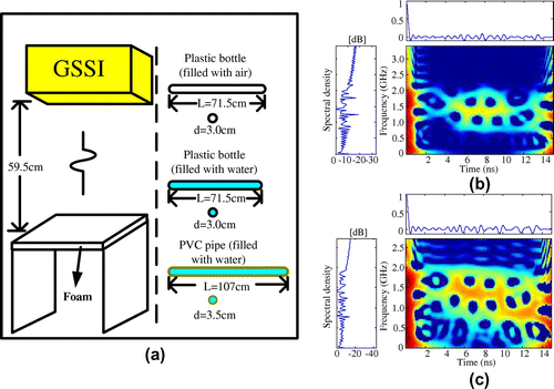
Figure 6. (a) Experiment scenario for water-filled crack in free space. (b) The SPWV distribution of the impulse responses from water-filled plastic bottle. (c) From water-filled PVC pipe.

Table 4. Estimated width for cracks in free space.

Figure 7. (a) Experiment scenario for subsurface water-filled crack. (b) The SPWV distribution of the impulse responses from water-filled PVC pipe. (c) From water-filled plastic bottle with d = 5.7 cm.
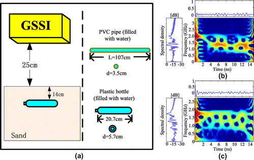
Figure 7. (a) Experiment scenario for subsurface water-filled crack. (b) The SPWV distribution of the impulse responses from water-filled PVC pipe. (c) From water-filled plastic bottle with d = 5.7 cm.

Table 5. Estimated width for subsurface cracks.