1,275
Views
1
CrossRef citations to date
0
Altmetric
Quantum Optics

Why material slow light does not improve cavity-enhanced atom detection

, , , & ORCID Icon
Pages 723-729 | Received 02 May 2017, Accepted 01 Sep 2017, Published online: 06 Oct 2017

Figures & data

Figure 1. Cavity spectrum with EIT. The normalized cavity photon number is plotted as a function of probe detuning. The solid red curve is the solution of the master equation, the dashed blue curve is the approximation from Equations (Equation3) and (Equation4), and the grey curve is for the empty cavity. The parameters were (G,W,κ,γ)=2π×(100,20,10,3) MHz, η=κ/1000, and Γ=γ/1000, as defined in the text. (a) full spectrum across all three normal modes. (b) central feature due to EIT.
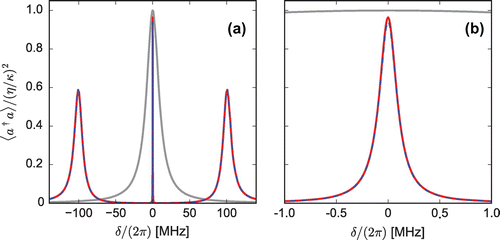
Figure 1. Cavity spectrum with EIT. The normalized cavity photon number is plotted as a function of probe detuning. The solid red curve is the solution of the master equation, the dashed blue curve is the approximation from Equations (Equation3(3) ρEG=Gαδ+iΓ(W/2)2-δ2+γΓ-iδ(γ+Γ),(3) ) and (Equation4(4) α=ηκ-iδ-iGρEG/α.(4) ), and the grey curve is for the empty cavity. The parameters were (G,W,κ,γ)=2π×(100,20,10,3) MHz, η=κ/1000, and Γ=γ/1000, as defined in the text. (a) full spectrum across all three normal modes. (b) central feature due to EIT.

Figure 2. Cavity ringdown with EIT. All parameters are the same as in Figure , with δ=0 and η0 at time t=0. The red curve is the full solution of the master equation, the blue dashed curve is an exponential decay with rate given by Equation (Equation8), and the grey curve is for an empty cavity. (a) Full ringdown trace (note the logarithmic scale). (b) Transient oscillation for early times.
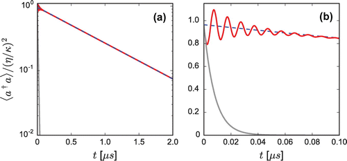
Figure 2. Cavity ringdown with EIT. All parameters are the same as in Figure 1, with δ=0 and η→0 at time t=0. The red curve is the full solution of the master equation, the blue dashed curve is an exponential decay with rate given by Equation (Equation8(8) R=2κ′ng.(8) ), and the grey curve is for an empty cavity. (a) Full ringdown trace (note the logarithmic scale). (b) Transient oscillation for early times.

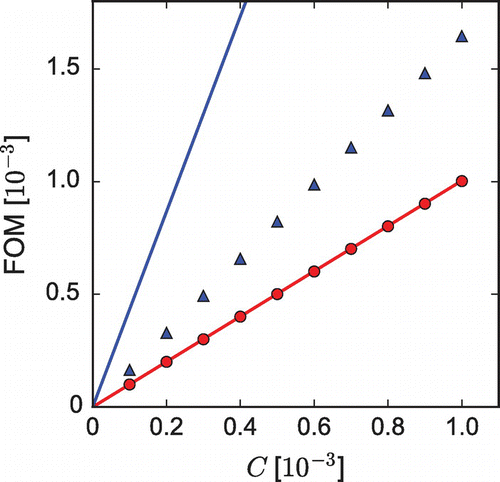
Figure 3. Figure of merit for cavity ringdown, as a function of 2LA cooperativity. Red circles/blue triangles show FOM from Equation (Equation13) obtained from numerical simulations with/without the 3LA slow light, where simulated CRD signals were fit to exponential decays at long times, ignoring initial transients. The 3LA slow light effect used the parameters of Figures  and . Solid lines are the predictions from Equation (Equation12).

Figure 3. Figure of merit for cavity ringdown, as a function of 2LA cooperativity. Red circles/blue triangles show FOM from Equation (Equation13(13) FOM≡R(C)-R(0)R(0).(13) ) obtained from numerical simulations with/without the 3LA slow light, where simulated CRD signals were fit to exponential decays at long times, ignoring initial transients. The 3LA slow light effect used the parameters of Figures 1 and 2. Solid lines are the predictions from Equation (Equation12(12) R=2κ′+g2/γng-g2/γ2.(12) ).

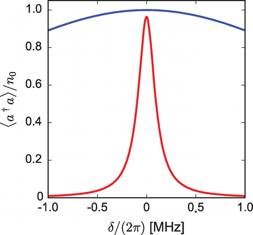
Figure 4. Purcell effect with (red, narrow) and without (blue, broad) slow light. The parameters were the same as in Figures  and , with g=2π×0.1 MHz and w=γ/1000. The scaling factor, n0=(wg)2/(2κγ)2, is the same for both curves.

Figure 4. Purcell effect with (red, narrow) and without (blue, broad) slow light. The parameters were the same as in Figures 1 and 2, with g=2π×0.1 MHz and w=γ/1000. The scaling factor, n0=(wg)2/(2κγ)2, is the same for both curves.