
Figures & data
Table 1. Chemical composition of the AISI-304L ASS (Weights%).
Figure 1. LOM images of the ASS (AISI-304L) at different processing states: (a) as received, (b) cold-rolled with the 25% height reduction (CR25), (c) BSE image of the CR25 sample, and (d) mean ferromagnetic phases contents measured by two different methods [Citation31].
![Figure 1. LOM images of the ASS (AISI-304L) at different processing states: (a) as received, (b) cold-rolled with the 25% height reduction (CR25), (c) BSE image of the CR25 sample, and (d) mean ferromagnetic phases contents measured by two different methods [Citation31].](/cms/asset/ad57893b-1bcd-4220-81e9-fca40353b70d/twld_a_2182728_f0001_c.jpg)
Figure 2. Schematic diagram of TMW system with a pneumatic hammer.
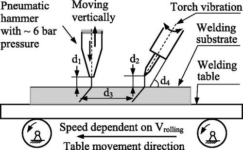
Table 2. Processing parameters of the TMW system in this work.
Table 3. Processing parameters and the related heat inputs (J/mm) of the TMW and TIG welding experiments on the AISI-304L ASSs.
Figure 3. 3D schematic diagram of the TIG bead-on-plate semi-weld with dimensions: A—semi area, W—semi width, and D—depth of the FZ observed at the cross-section. In addition, the red arrow indicates the TIG welding trajectory.
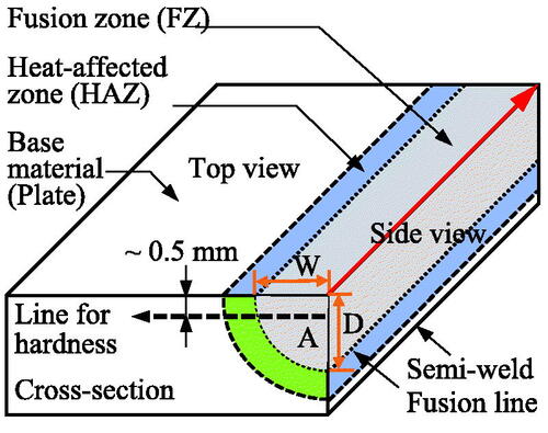
Figure 4. Evolution of the FZ dimensions (i.e. width-W, depth-D, and area-A at the cross-section) of TIG bead-on-plate welds of the AISI 304L ASS to heat inputs.
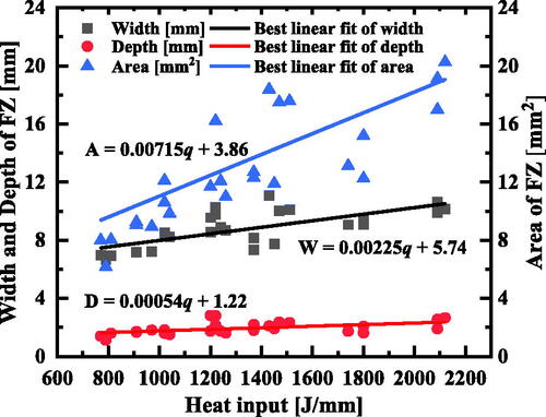
Figure 5. Comparasion of the mean ferromagnetic phases content between the TIG and TMW welds of the AISI 304L ASS at various heat inputs at the FZ.
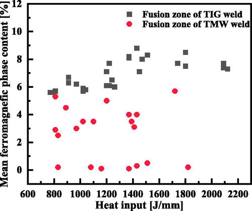
Figure 6. Low magnified LOM images of two different bead-on-plate welds of cold-rolled AISI 304L with 25% thickness reduction: (a) a TIG weld and (b) a TMW weld obtained with 20 mm offset at a constant TIG welding current of 150 A, and welding speed of 12 cm/min.
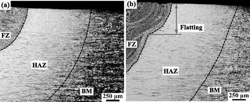
Figure 7. LOM images of the FZ and HAZ of TIG and TMW bead-on-plate welds on the material of cold-rolled AISI 304L by 25% thickness reduction (CR25) at the constant welding current of 150 A, and welding speed of 12 cm/min, and additionally with 20 and 30 mm offsets between the TIG torch and hammer for the TMW welds. (a–c) are in FZ, and (d–f) are in the HAZ.
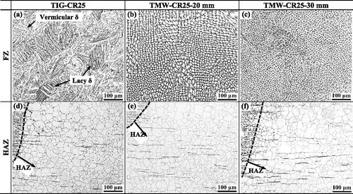
Figure 8. Large heterogeneous microstructure of TMW bead-on-plate weld top region (side view of FZ) of the cold-rolled AISI 304L subjected to a 25% thickness reduction (CR25) at a welding current of 150 A, a welding speed of 12 cm/min, and an offset of 30 mm.
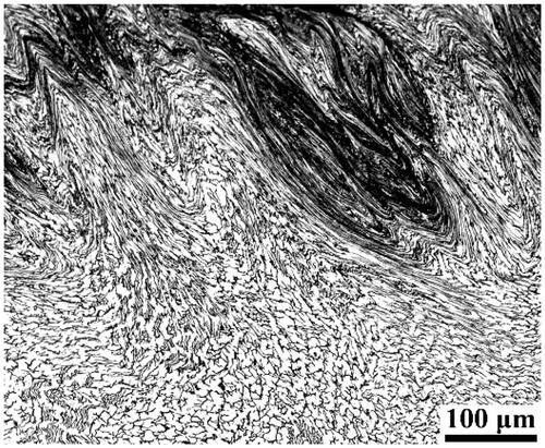
Figure 9. Comparasion of the width, depth, and mean ferromagnetic phase content in the FZ and mean grain size of HAZ of both TIG welds and TMW welds of the AISI 304L ASS at different processing conditions.
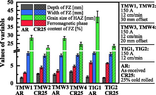
Figure 10. Mean grain size of the HAZ in TIG and TMW welds: (a) TIG welds at different initial material states, and (b) in the TMW welds of CR25 AISI 304L at various heat inputs.
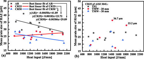
Figure 11. Hardness profiles of the TMW weld of as-received AISI 304L at a welding current of 150 A, a welding speed of 12 cm/min, and a 20 mm offset between the hammer and TIG torch.
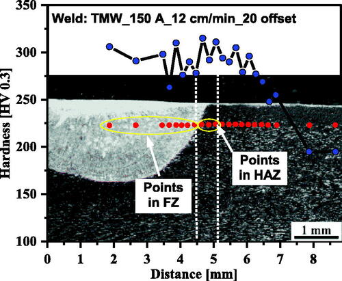
Figure 12. Comparasion of the hardness in the TIG and TMW welds of ASS AISI 304L to heat inputs for different positions of welds (a) FZ, (b) HAZ, and (c) for different offsets of the TMW welding.
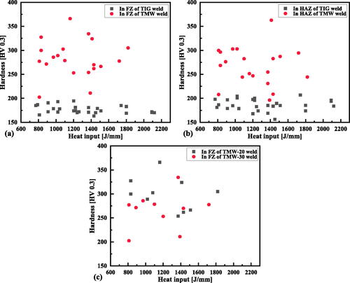
Figure A-1. LOM observations (photographed in black and white) of the as-received (a) and cold-rolled with 25% thickness reduction (b) of AISI 304L ASS at initial conditions.
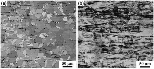
Table A-1. The calculated time t8/5 (s) of performed TMW and TIG welding tests on the ASS AISI-304L