
Figures & data
Table 1. Chemical composition (in wt.%) of the wires and base plate.
Table 2. Different combination of Ar and CO2 gases for single layer deposition with solid (SW) and metal-cored (MCW) wires.
Table 3. Parameters used for deposition of single-layer deposits.
Table 4. Welding parameters used for evaluation of silicon islands in the metal cored wire.
Table 5. A Summary of tests performed to compare the standard (MCW) and the modified metal cored wire (MCW-m).
Figure 1. Cross-sectional profiles of single-layer deposits produced using solid wire with different combinations of Ar and CO2 gases.
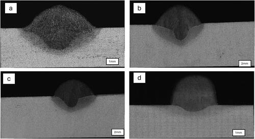
Figure 2. Cross-sectional profiles of single-layer deposits produced using metal-cored wire with different combinations of Ar and CO2 gases.
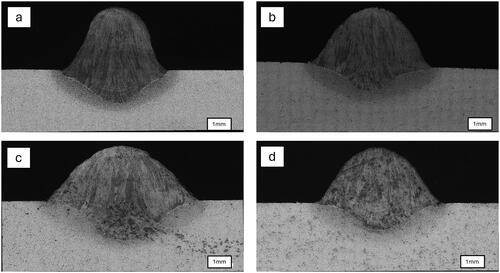
Figure 3. Silicon islands formation in the deposits produced using standard and modified metal cored wires in the horizontal position. Note the change in location and amount of silicates.
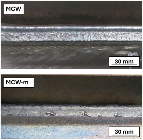
Table 6. Chemical composition (in wt.%) of the original and modified metal cored wires.
Table 7. Tensile and Charpy results in as-welded and after PWHT for the MCW-m and MCW wires.