Figures & data
Figure 1. Representation of a SSL and the corresponding safety zone enclosing one link of the considered manipulator. The path-consistent stop trajectory of the end-effector is shown with a thicker line with respect to the nominal trajectory.
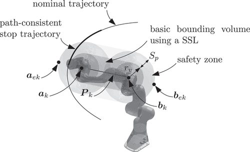
Figure 2. Example of nominal and path-consistent stop trajectory (with five and four-degree parameterization): joint position, velocity and acceleration.
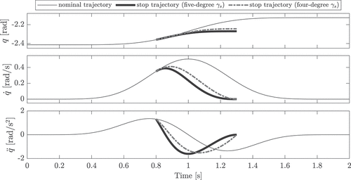
Figure 3. Frames of an example simulation in which the manipulator performs a random trajectory, while the human cyclically enters the robot workspace. A safety stop of the robot is highlighted with grey background.
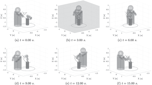
Figure 4. Example trajectory: position, velocity and torque for joint 1. Safety stops and uncertain torque bounds are represented as shaded areas, whereas vertical solid lines indicate target points.\.
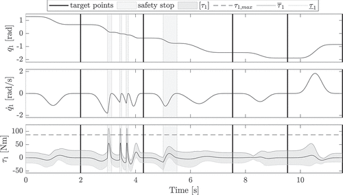
Figure 6. Numerical results: stop time (a), radii of the safety zones (b), total task time (c), and number of robot stops (d) for different bounds of the maximum payload.
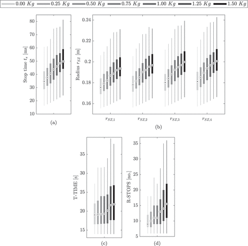
Table 1. Mean values of the quantitative metrics stop time, radii of the safety zones, total task time, and number of robot stops, as well as the percentage difference with respect to the nominal case () for different bounds of the maximum payload.
Table A1. Nominal parameters of the Franka Emika robot used in the numerical simulations from (Franka Emika Citation2022). ,
,
and
are the parameters of the modified Denavit – Hartenberg convention (Craig Citation2006);
represents the mass;
,
,
are the center of mass coordinates;
,
,
,
,
,
are the inertia tensor elements;
,
are the viscous and coulomb friction model coefficients (obtained by fitting the parameters of the friction model found in (Gaz et al. Citation2019.)).

