
Figures & data
Figure 1. The assembly tool is available at https://github.com/CoMeMak/assembly.
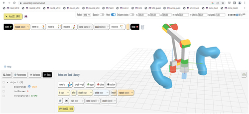
Figure 2. High-level architecture of Assembly.
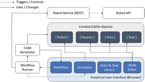
Figure 3. Communication architecture.
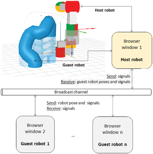
Figure 4. Rendering capabilities in Assembly: one host and one guest robot (left); one host robot with human arms and protection window (middle); one host and two guest robots (right).
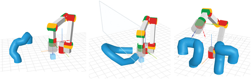
Figure 5. Replicated virtual tubes (RVT) technique with height-adjusted intersection points.
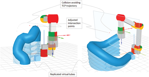
Figure 6. Dynamic toolpath planning using a neural network model for predicting the lamé curve parameters.
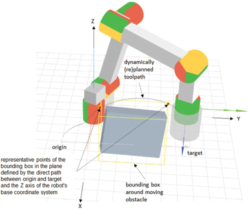
Figure 7. A.) different possible shapes of the lamé curve equation; b.) formulation of the optimization problem in terms of the lamé curve equation; c.) projection of the obstacle onto a 2D-plane aligned with the direct path from origin to target on the X’ axis and with the Z axis of the robot’s coordinate system on the Y’ axis.
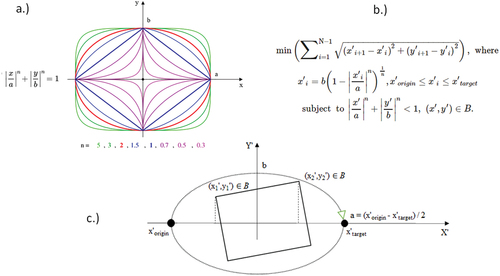
Figure 8. Motion planning strategy and architecture used in Assembly.
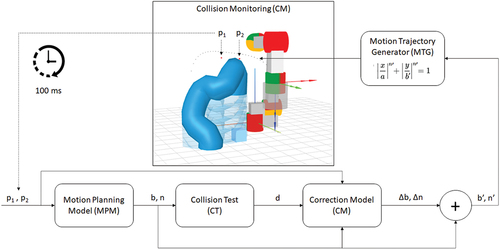
Figure 9. Safe problem space (SPS) of the MPM model.
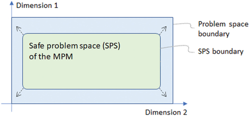
Figure 10. Human–robot collaboration (HRC) application from bayerdynamic® (Robotiq and Baserdynamic, Citation2022).
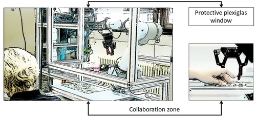
Figure 11. Simulated human-robot collaboration application scenario from bayerdynamic®.
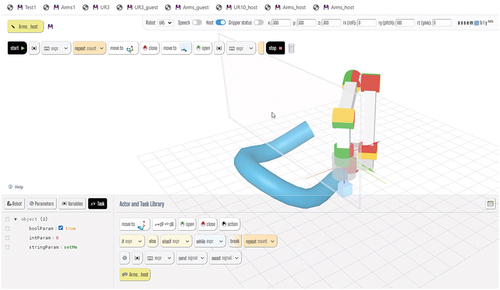
Figure 12. Movement sequence for picking and placing the blue cube in the human-robot collaboration region in the context of the bayerdynamic® scenario.
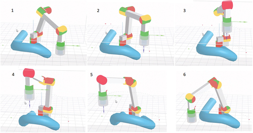
Table 1. Results of the performance evaluation for the human-robot collaboration scenario.
Figure 13. Siemens CPPS (Mert Citation2018; Schmidbauer et al. Citation2020). A KUKA iiwa and a UR3 collaborative robot are fixed on one of the sides of a hexagonal workbench. (1) the conveyor provides unfinished parts, and the KUKA robot performs and assembly step before transporting the work piece to a designated assembly jig (2). Here, the UR3 robot screws in the case and the KUKA robot transports the product for inspection (3). Finally, the KUKA robot places the finished part into a boxing jig (4), where a human worker performs the packaging.
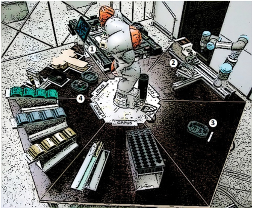
Figure 14. The simulated multi-robot scenario with corresponding programs.
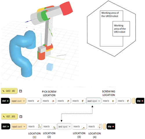
Table 2. Results of the performance evaluation for the multi-robot simulation scenario.
Table 3. Comparison of key performance indicators of ASMP, CASMP, and MRDF (with and without RF).