
Figures & data
Table 1. Comparison of the tradeoffs between the memory- and storage-based QCS.
Figure 1. The architecture of the quantum circuit simulator.
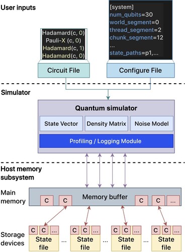
Figure 2. An example output of the profiling data offered by our simulator.
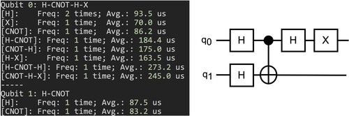
Table 2. The parameters used by the proposed quantum circuit simulator.
Table 3. Configuration of hardware and software for experiments.
Figure 3. An empirical workflow to determine proper settings for the File, Middle, and Chunk segments for an N-qubit system whose representation is shown in Figure .
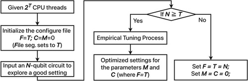
Figure 4. An example of the representation of qubits, where the 11-qubit is partitioned into three segments, File, Middle, and Chunk segments that can be used to point to the corresponding quantum state stored in the state file.
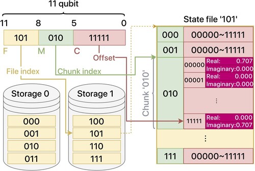
Figure 5. For the 11-qubit system as an example, the qubit representation and the corresponding accesses to the qubit states by the threads, where targ is within a middle segment.
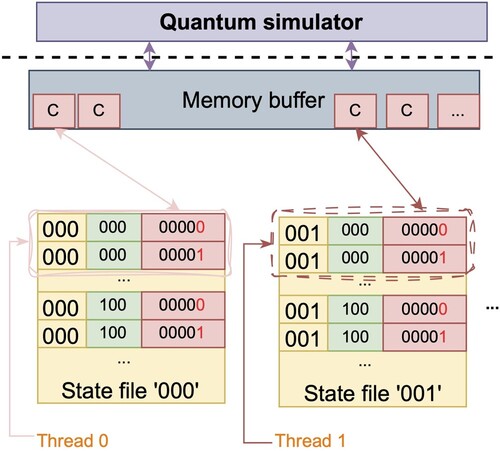
Figure 6. For the 11-qubit system as an example, the qubit representation and the corresponding accesses to the qubit states by the threads, where targ is within a chunk segment.
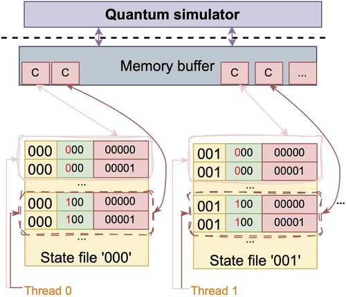
Figure 7. For the 11-qubit system as an example, the qubit representation and the corresponding accesses to the qubit states by the threads, where targ is within a file segment.
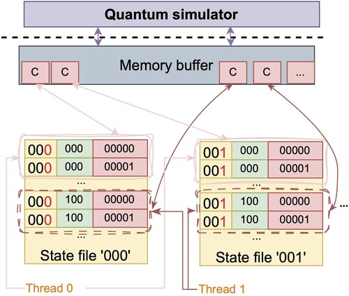
Figure 8. Illustration of the accesses to the quantum state files by our proposed simulator through a standard I/O (left) or a direct I/O interface (right).
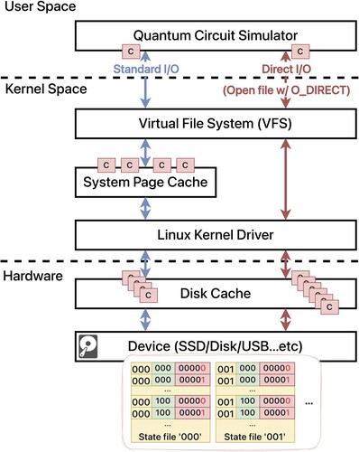
Figure 9. A comparison between QuEST and our simulator is performed for the Hadamard gate simulation in microseconds, with a range of qubits from 21 to 39.
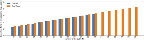
Figure 10. Ultizing 64 cores to explore a proper chuck segment value.
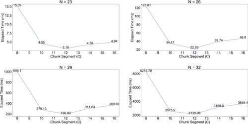
Table 4. Evaluating the performance impact of different file segments (unit: s).
Table 5. Evaluating a proper thread segment value (unit: s).
Table 6. The elapsed time of the standard and direct IO (unit: s).
Table 7. The quantum circuit simulation time on QFT and five-level QAOA (unit: s).