2,846
Views
24
CrossRef citations to date
0
Altmetric
Articles

Removal of fluoride from aqueous solution by TiO2 and TiO2–SiO2 nanocomposite

, , &
Pages 25-32 | Received 04 Nov 2016, Accepted 05 Dec 2016, Published online: 22 Dec 2016

Figures & data

Figure 1. SEM images of TiO2(T) (a), TiO2(S) (b), SiO2–TiO2(T) (c), and SiO2–TiO2(S) (d).

Figure 1. SEM images of TiO2(T) (a), TiO2(S) (b), SiO2–TiO2(T) (c), and SiO2–TiO2(S) (d).

Table 1. Specific surface area of the four TiO2 adsorbents.

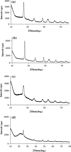
Figure 2. XRD spectra of TiO2(T) (a), TiO2(S) (b), SiO2–TiO2(T) (c), and SiO2–TiO2(S) (d).

Figure 2. XRD spectra of TiO2(T) (a), TiO2(S) (b), SiO2–TiO2(T) (c), and SiO2–TiO2(S) (d).

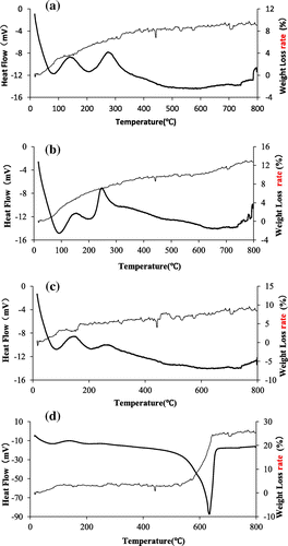
Figure 3. TG-DTA of TiO2(T) (a), TiO2(S) (b), SiO2–TiO2(T) (c), and SiO2–TiO2(S) (d).

Figure 3. TG-DTA of TiO2(T) (a), TiO2(S) (b), SiO2–TiO2(T) (c), and SiO2–TiO2(S) (d).

Figure 4. Continuous sorption of TiO2(T) (a), TiO2(S) (b), SiO2–TiO2(T) (c), and SiO2–TiO2(S) (d).
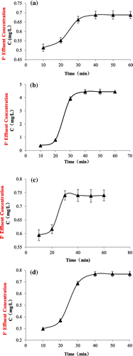
Notes: 200 mg adsorbent was put into a 50 mL centrifuge tube filled with 25 mL fluoride solution of certain concentration, and then the tube was oscillated in the gyrotron oscillator for 10 min. After centrifugation and filtration, the supernatant was obtained. The concentration of fluoride in the supernatant was measured. The adsorbent was then added into a new solution of 25 mL fluoride to repeat the sorption process until the fluoride concentration of the supernatant reached constant.
Figure 4. Continuous sorption of TiO2(T) (a), TiO2(S) (b), SiO2–TiO2(T) (c), and SiO2–TiO2(S) (d).

Figure 5. Adsorption capacity (a) and adsorption rate (b) of TiO2(T) and SiO2–TiO2(T) to fluoride with different initial fluoride concentration.
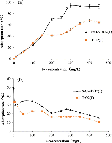
Notes: 20 mg adsorbent was added into 25 mL fluoride solution with concentration varying from 1 mg/L to 500.0 mg/L to study the adsorption capacity and adsorption rate of the materials.
Figure 5. Adsorption capacity (a) and adsorption rate (b) of TiO2(T) and SiO2–TiO2(T) to fluoride with different initial fluoride concentration.

Figure 6. Adsorption capacity (a) and adsorption rate (b) of TiO2(S) and SiO2–TiO2(S) to fluoride with different initial fluoride concentration.
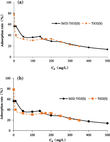
Notes: 20 mg adsorbent was added into 25 mL fluoride solution with concentration varying from 1 mg/L to 500.0 mg/L to study the adsorption capacity and adsorption rate of the materials.
Figure 6. Adsorption capacity (a) and adsorption rate (b) of TiO2(S) and SiO2–TiO2(S) to fluoride with different initial fluoride concentration.

Figure 7. Effect of pH on fluoride adsorption onto TiO2(T), TiO2(S), SiO2–TiO2(T), and SiO2–TiO2(S).
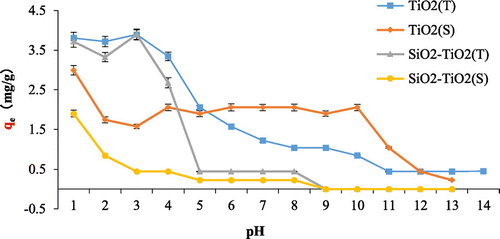
Notes: 5 mg/L fluoride solution of different pH (1–14) were obtained with NaOH or HCl adjustment to study the effect of pH.
Figure 7. Effect of pH on fluoride adsorption onto TiO2(T), TiO2(S), SiO2–TiO2(T), and SiO2–TiO2(S).

Figure 8. Effects of coexisting ions on fluoride adsorption onto TiO2(T) (a) and TiO2(S) (b).
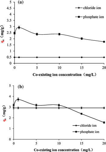
Notes: Cl and of 1.0, 5.0, 10.0 and 15.0, 20.0 mg/L were used as the coexisting ion with the 5 mg/L fluoride to study the effects of coexisting ions.
Figure 8. Effects of coexisting ions on fluoride adsorption onto TiO2(T) (a) and TiO2(S) (b).

Figure 9. Adsorption isotherms of fluoride on TiO2(T) (a), TiO2(S) (b), SiO2–TiO2(T) (c), and SiO2–TiO2(S) (d).
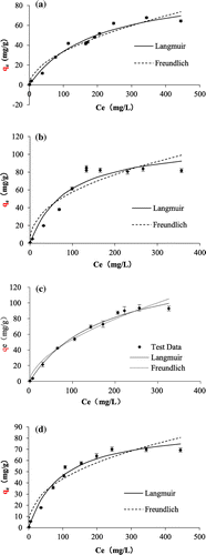
Note: The isotherm data were fitted by Langmuir and Freundlich isotherm equation.
Figure 9. Adsorption isotherms of fluoride on TiO2(T) (a), TiO2(S) (b), SiO2–TiO2(T) (c), and SiO2–TiO2(S) (d).

Table 2. Best-fit parameters of adsorption isotherms of fluoride onto the TiO2 composites.