
Figures & data
Figure 1. Examples of turbine component-feature specimen tests.
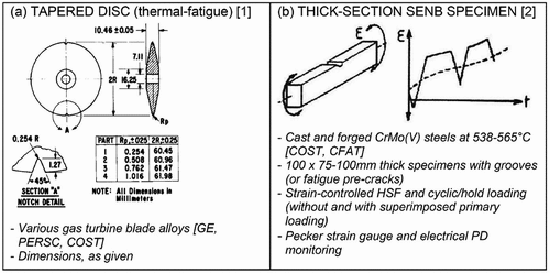
Figure 2. Examples of isothermal thick-wall section pressure vessel component-feature specimen benchmark tests.
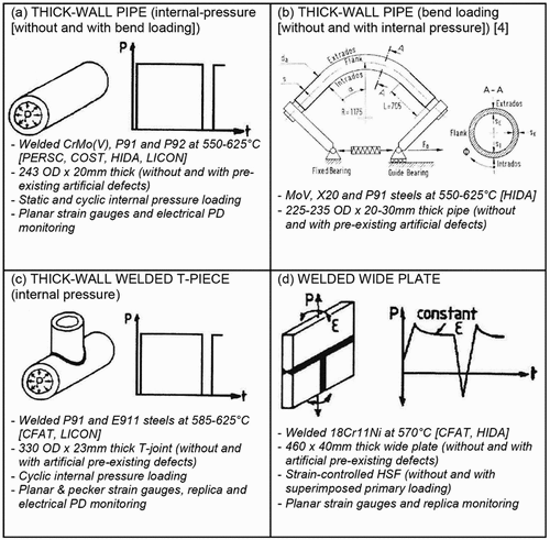
Figure 3. Schematic representation of influence of relatively slow (continuous grey lines) and relatively fast (solid black broken lines) heating/cooling rates on thermal strain generation at a critical turbine feature location.
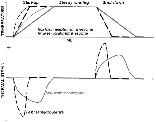
Figure 4. Schematic representation of simplified HP turbine service cycle adopted for isothermal benchmark testing.
Figure 5. Example of turbine component-feature specimen, service-cycle TMF testing arrangement.
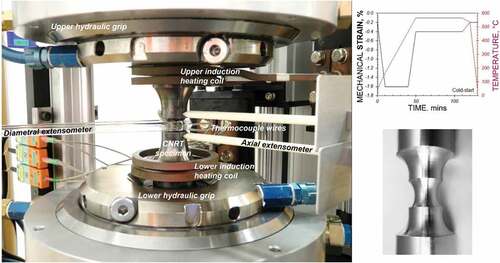
Figure 6. Representations of (a) hot-start, (b) warm-start, and (c) cold-start TMF service cycles for a blade root fixing in a high temperature 1%CrMoV turbine rotor (as adopted in [12]).
![Figure 6. Representations of (a) hot-start, (b) warm-start, and (c) cold-start TMF service cycles for a blade root fixing in a high temperature 1%CrMoV turbine rotor (as adopted in [12]).](/cms/asset/18c85159-650c-4a8c-84b5-db987be2348d/ymht_a_2173717_f0006_c.jpg)
Figure 7. Common steps in a number of published creep-fatigue assessment procedures (e.g. [20–23].
![Figure 7. Common steps in a number of published creep-fatigue assessment procedures (e.g. [20–23].](/cms/asset/0ec92003-42c3-4465-b7f1-afeea92fa7f7/ymht_a_2173717_f0007_b.gif)
Figure 8. Damage development in 1%CrMoV TMF specimens subjected to (a) a hot-start TMF cycle, (b) a warm-start TMF cycle, and (c) a cold-start TMF cycle (see ).
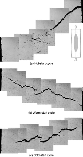
Figure 9. Comparison of enhanced FEA rotor blade-fixing root (numerical) stress/strain hysteresis response with that applied (experimental) in a feature specimen, service-cycle TMF test [13].
![Figure 9. Comparison of enhanced FEA rotor blade-fixing root (numerical) stress/strain hysteresis response with that applied (experimental) in a feature specimen, service-cycle TMF test [13].](/cms/asset/4f247e33-5774-4d6d-9b0e-845527819c30/ymht_a_2173717_f0009_c.jpg)