
Figures & data
Figure 1. (A) Posteroanterior measurement guidelines: (1) The center of the radial shaft is determined at 3 cm and 5 cm below the mid-region of the proximal lunate articular surface. This line represents the central axis of the radius. (2) A line perpendicular to the central long axis of the radius is drawn at the level of the most distal aspect of the radial articular surface. (3) A line perpendicular to the central long axis of the radius is drawn at the level of the ulnar margin of the distal radial articular surface. (4) The radial and ulnar margins of the distal radial articular surface are connected. (5) A line perpendicular to the central long axis of the radius is drawn at the level of the distal ulnar articular surface. (B) Lateral measurement guidelines: (1) The center of the radial shaft is determined at 3 cm and 5 cm below the mid-region of the proximal lunate articular surface. This line represents the central long axis of the radius. (2) A line perpendicular to the central long axis of the radius is drawn at a convenient level. (3) The dorsal and anterior margins of the distal radial articular surface are connected. (C) Step-off and gap measurement. (1) Step-off at the articular surface of the distal radius was measured parallel to the central long axis of the radius by drawing perpendicular lines from the most distal margin of each side of the articular incongruence. (2) Gap deformity was measured along a perpendicular line to the central long axis of the radius. UV: ulnar variation; RL: radial length; RI: radial inclination; DT: dorsal tilt; SL: scapholunate ligament; DRUJ: distal radioulnar joint.
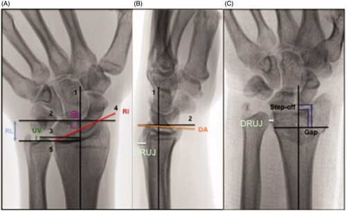
Table 1. Reference values, error magnitudes for radiological measurements and SDCs and MICs for CROs and PROs.
Table 2. Patient characteristics.
Table 3. Radiological measurements at baseline, 6 weeks and follow up.
Table 4. Radiological measurements of the inured and uninjured wrist at follow-up.
Table 5. CROs derived from injured and uninjured wrist at follow-up.
Table 6. PROs at follow up compared to measurements of healthy controls.
Table 7. Univariable regression analyses of radiological measurements and CROs.
Table 8. Univariable regression analyses for radiological measurements and PROs.
Table 9. Multivariable regression analyses of radiological measurements and CROs.
Table 10. Multivariable linear regression analysis for radiological measurements and PROs.