Figures & data
Figure 1. Flow diagram of study identification, inclusion and exclusion.
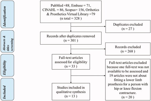
Table 1. Quality assessment results of 13 case reports based on the Joanna Briggs Institute critical appraisal checklist.
Figure 2. A shows a socket connected with a crutch; B shows a socket connected with a thigh corset, a shank, and foot by metal sidebars; C shows a transtibial socket connected with a shank and a foot.
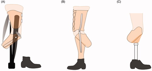
Figure 3. A shows a bent knee pylon; B shows a kneeling bearer connected with a peg leg.
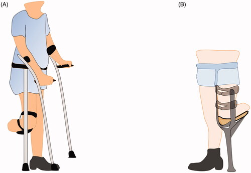
Table 2. Summary of prostheses designs and fitting results.
Figure 4. A bent transfemoral socket attached to the wooden shank via the sidebars with an extra joint allowing more flexion when seated.
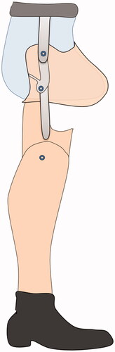
Figure 5. A shows a transtibial amputee sitting with a bent knee prosthesis without an extra joint; B shows a transfemoral amputee sitting with a bent hip prosthesis with a flexion contracture plate; C shows compensation material to offset the socket; D and E show transtibial and transfemoral amputees with an extra joint underneath the socket to increase the seating cosmetic.
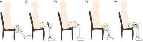
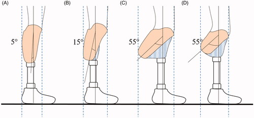
Figure 6. shows different degrees of transtibial socket flexion and path of the weight line dropping from mid socket and passing through the ankle. The distance between the 2 dotted lines shows the bulkiness of the socket in which the greatest distance is the bulkiest prosthesis. For the same residual limb length, the bulkiest is the most flexed socket (C > B > A), and for the same angle, it is the longer residual limb length (C > D).
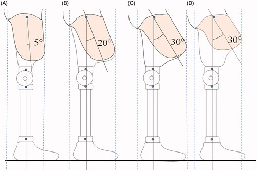
Figure 7. shows different degrees of transfemoral socket flexion and path of the weight line dropping from trochanter, falling in front of the knee and passing through the ankle. The distance between the two dotted lines shows the bulkiness of the socket in which the greatest distance is the bulkiest prosthesis. For the same residual limb length, most bulkiness occurs in the most flexed socket (C > B > A) and, for the same angle, it occurs in the longer residual limb (C > D).