531
Views
5
CrossRef citations to date
0
Altmetric
Papers

Altered pore properties and kinetic changes in mutants of the Vibrio cholerae Porin OmpU

, &
Pages 498-505 | Received 28 Jun 2008, Published online: 09 Jul 2009

Figures & data

Figure 1.  Mutations investigated in this study. (A) Location of the mutated residues in the homology model of OmpU Citation[25], as visualized using the VMD software Citation[37]. (B) Table of homologous residues in V. cholerae OmpU, and E. coli OmpF and OmpC.

Figure 1.  Mutations investigated in this study. (A) Location of the mutated residues in the homology model of OmpU Citation[25], as visualized using the VMD software Citation[37]. (B) Table of homologous residues in V. cholerae OmpU, and E. coli OmpF and OmpC.

Figure 2.  Electrophysiological behavior. Representative current traces of WT and the investigated mutants were obtained at a pipette potential of +50 mV. ‘O3’ marks the current level through all three open monomers; ‘C1’ marks the current level upon closure of 1 monomer.
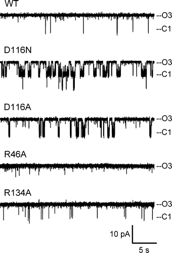
Figure 2.  Electrophysiological behavior. Representative current traces of WT and the investigated mutants were obtained at a pipette potential of +50 mV. ‘O3’ marks the current level through all three open monomers; ‘C1’ marks the current level upon closure of 1 monomer.

Figure 3.  Dwell time analysis. The average (± SEM) dwell times of the current at the O3 and the C1 levels are shown (n=3–5, except for R134A where n=2).
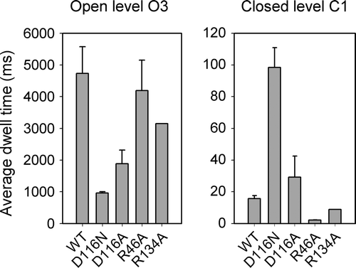
Figure 3.  Dwell time analysis. The average (± SEM) dwell times of the current at the O3 and the C1 levels are shown (n=3–5, except for R134A where n=2).

Figure 4.  Trimeric conductance. Current-voltage plots of the conductance of a single trimer of WT and each of the investigated OmpU mutants. Three to eight patches were used, depending on the protein, but not all voltages were repeated. Error bars (SEM) are given only for data points with at least three measurements.
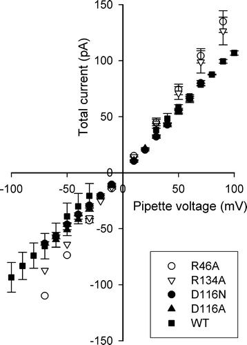
Figure 4.  Trimeric conductance. Current-voltage plots of the conductance of a single trimer of WT and each of the investigated OmpU mutants. Three to eight patches were used, depending on the protein, but not all voltages were repeated. Error bars (SEM) are given only for data points with at least three measurements.

Table I.  Electrophysiological parameters obtained for WT and mutant OmpU.

Figure 5.  Sub-conductance states in OmpU mutants. Representative current traces of the D116 mutants and a D116N monomer are shown on an expanded time scale to highlight transitions to current levels of a conductance smaller than the monomeric conductance, as marked by a dashed line.
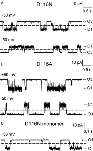
Figure 5.  Sub-conductance states in OmpU mutants. Representative current traces of the D116 mutants and a D116N monomer are shown on an expanded time scale to highlight transitions to current levels of a conductance smaller than the monomeric conductance, as marked by a dashed line.

Table II.  Comparison of properties for the different mutants relative to WT.

Reprints and Corporate Permissions

Please note: Selecting permissions does not provide access to the full text of the article, please see our help page How do I view content?

To request a reprint or corporate permissions for this article, please click on the relevant link below:

Academic Permissions

Please note: Selecting permissions does not provide access to the full text of the article, please see our help page How do I view content?

Obtain permissions instantly via Rightslink by clicking on the button below:

If you are unable to obtain permissions via Rightslink, please complete and submit this Permissions form. For more information, please visit our Permissions help page.