1,216
Views
6
CrossRef citations to date
0
Altmetric
Articles

A critical review of the Kibyra Fault (Burdur-Fethiye Shear Zone, SW Turkey)

ORCID Icon, ORCID Icon, , &
Pages 91-102 | Received 26 Aug 2016, Accepted 07 Apr 2017, Published online: 25 Apr 2017

Figures & data

Figure 1. (a) Simplified tectonic map of the Turkey compiled from Yaltırak İşler, Aksu, and Hiscott (Citation2012). TEF: Thrace-Eskişehir Fault, NAF: North Anatolian Transform Fault, EAFZ: East Anatolian Fault Zone, DSFZ: Dead Sea Fault Zone, IA: Isparta Angle, BFSZ: Burdur-Fethiye Shear Zone. Rectangle indicates Figure 1b. (b) Simplified fault map of the southwestern Turkey and location of the study area. BFSZ: Burdur-Fethiye Shear Zone, PSFZ: Pliny-Strabo Fault Zone, GYFZ: Gökova-Yeşilüzümlü Fault Zone, AB: Acıpayam Basin, AGB: Acıgöl Basin, BB: Burdur Basin, TB: Tefenni Basin, EB: Eşen Basin, GNKG: Gökova-Nisyros-Karpathos Graben.
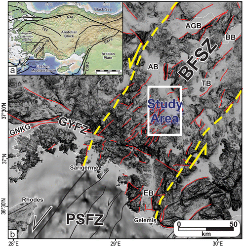
Figure 1. (a) Simplified tectonic map of the Turkey compiled from Yaltırak İşler, Aksu, and Hiscott (Citation2012). TEF: Thrace-Eskişehir Fault, NAF: North Anatolian Transform Fault, EAFZ: East Anatolian Fault Zone, DSFZ: Dead Sea Fault Zone, IA: Isparta Angle, BFSZ: Burdur-Fethiye Shear Zone. Rectangle indicates Figure 1b. (b) Simplified fault map of the southwestern Turkey and location of the study area. BFSZ: Burdur-Fethiye Shear Zone, PSFZ: Pliny-Strabo Fault Zone, GYFZ: Gökova-Yeşilüzümlü Fault Zone, AB: Acıpayam Basin, AGB: Acıgöl Basin, BB: Burdur Basin, TB: Tefenni Basin, EB: Eşen Basin, GNKG: Gökova-Nisyros-Karpathos Graben.

Figure 2. Geological map and X–Y geological cross-section of the study area. The lithological properties and ages of the basement rocks were derived from 1/500000 Denizli sheet geological map of General Directorate of Mineral Research and Exploration (Şenel, Citation2002) and the contacts were redrawn by using DEMs, satellite images and field observations.
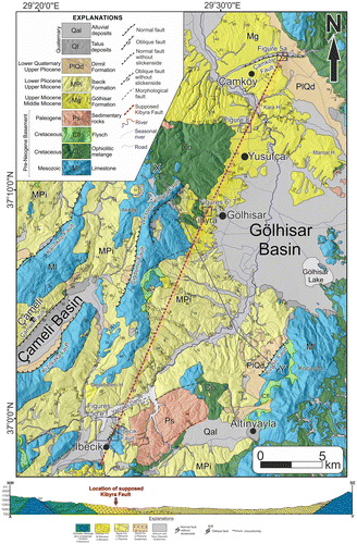
Figure 2. Geological map and X–Y geological cross-section of the study area. The lithological properties and ages of the basement rocks were derived from 1/500000 Denizli sheet geological map of General Directorate of Mineral Research and Exploration (Şenel, Citation2002) and the contacts were redrawn by using DEMs, satellite images and field observations.

Figure 3. (a) 3D satellite image of the Çiğdemli Fault. Yellow arrows indicate the fault trace. (b) Claystones and limestones of İbecik Formation with high angles. (c) Quaternary talus deposits in front of the Kibyra Fault which was located to north-west of Kibyra. (d) S–-N topographic profile of the location where Çamköy Fault exists.
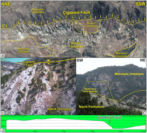
Figure 3. (a) 3D satellite image of the Çiğdemli Fault. Yellow arrows indicate the fault trace. (b) Claystones and limestones of İbecik Formation with high angles. (c) Quaternary talus deposits in front of the Kibyra Fault which was located to north-west of Kibyra. (d) S–-N topographic profile of the location where Çamköy Fault exists.

Figure 4. Seismotectonic map of the study area. Earthquake data from USGS (Citation2015).
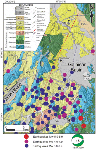
Figure 4. Seismotectonic map of the study area. Earthquake data from USGS (Citation2015).

Figure 5. (a) Miocene conglomerates and strike-slip faults. Yellow lines indicate the layers. (b) indicates the location of Figure b. (b) Fault plane of the strike-slip fault shown in Figure (a). Red line indicates the striation. (c) Fault plane of the İbecik Fault shown in Figure (d). Yellow line indicates the striation. (d) View of the İbecik Fault in the field. (e) View of the İbecik Fault on DEM. (f) View of the İbecik Fault on satellite image.
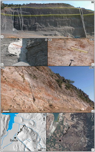
Figure 5. (a) Miocene conglomerates and strike-slip faults. Yellow lines indicate the layers. (b) indicates the location of Figure 5b. (b) Fault plane of the strike-slip fault shown in Figure 4(a). Red line indicates the striation. (c) Fault plane of the İbecik Fault shown in Figure 4(d). Yellow line indicates the striation. (d) View of the İbecik Fault in the field. (e) View of the İbecik Fault on DEM. (f) View of the İbecik Fault on satellite image.

Figure 6. (a) Aerial photo of the ancient stadium of Kibyra. Yellow dashed line indicates the artificial fill area. Red dashed line indicates the excavated area. c and d indicate the locations of Figure (c) and (d). (b) E–W cross-section of the southern part of the ancient stadium. (c) Boundary between bedrock and artificial fill. (d) Conglomerate blocks used during the construction of the eastern seat rows.
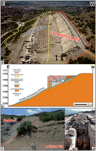
Figure 6. (a) Aerial photo of the ancient stadium of Kibyra. Yellow dashed line indicates the artificial fill area. Red dashed line indicates the excavated area. c and d indicate the locations of Figure 6(c) and (d). (b) E–W cross-section of the southern part of the ancient stadium. (c) Boundary between bedrock and artificial fill. (d) Conglomerate blocks used during the construction of the eastern seat rows.

Figure 7. (a) Trench excavated in front of the southern seat rows. Yellow dashed line indicates the supposed Kibyra Fault. (b) and (c) show the lowermost row and bottom of the stadium from different directions. Scale in the trench is 50 cm.
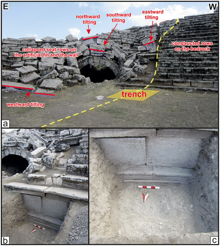
Figure 7. (a) Trench excavated in front of the southern seat rows. Yellow dashed line indicates the supposed Kibyra Fault. (b) and (c) show the lowermost row and bottom of the stadium from different directions. Scale in the trench is 50 cm.

Figure 8. (a) Satellite image of the trench site. Yellow dashed line indicates supposed Kibyra Fault. (b) Trench direction and geological units in the trench site. Yellow dashed line indicates supposed Kibyra Fault. (c) Simplified geological map and digital elevation model of the trench site. Green dashed line indicates supposed Kibyra Fault. (d) Northern wall of the trench (Coordinate: 37°13′11.45″N 29°31′55.35″E).
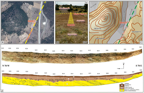
Figure 8. (a) Satellite image of the trench site. Yellow dashed line indicates supposed Kibyra Fault. (b) Trench direction and geological units in the trench site. Yellow dashed line indicates supposed Kibyra Fault. (c) Simplified geological map and digital elevation model of the trench site. Green dashed line indicates supposed Kibyra Fault. (d) Northern wall of the trench (Coordinate: 37°13′11.45″N 29°31′55.35″E).
Supplemental material

TGDA_1318001_Supplementary_material.pdf

Download PDF (3.5 MB)