3,841
Views
8
CrossRef citations to date
0
Altmetric
Articles

Building reconstruction from airborne laser scanning data

Pages 35-44 | Received 01 Jan 2013, Accepted 06 Feb 2013, Published online: 27 Mar 2013

Figures & data

Figure 1 General work-flow of building model reconstruction. It includes three main steps: building region detection, features extraction and model generation.
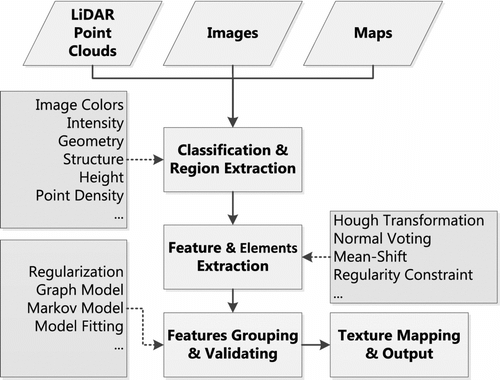
Figure 1 General work-flow of building model reconstruction. It includes three main steps: building region detection, features extraction and model generation.

Figure 2 The parameters of a plane for 3D Hough transform. Figure courtesy of Overby et al. Citation(21).
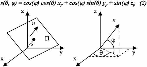
Figure 2 The parameters of a plane for 3D Hough transform. Figure courtesy of Overby et al. Citation(21).

Figure 3 Rule based roof detection to extract multiple-roofs simultaneously. The graph contains roof planes and points clustering in Hough space. Figure courtesy of Huang and Brenner Citation(23).
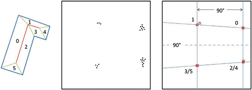
Figure 3 Rule based roof detection to extract multiple-roofs simultaneously. The graph contains roof planes and points clustering in Hough space. Figure courtesy of Huang and Brenner Citation(23).

Figure 4 The sizes of roofs are influenced by the detection sequence, (a) model with four same size planar surfaces, (b) sizes of detected results and (c) final results after competition.
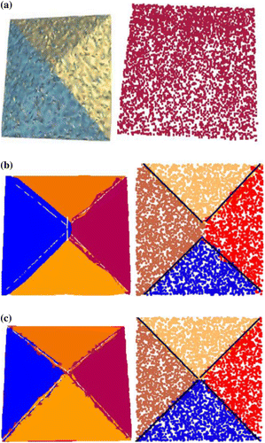
Figure 4 The sizes of roofs are influenced by the detection sequence, (a) model with four same size planar surfaces, (b) sizes of detected results and (c) final results after competition.

Figure 5 Real edges position of building. (a) The laser beam hits the edge of a building. (b) The correct position of edge should be close to p, not in the middle part of p and q 2.
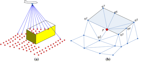
Figure 5 Real edges position of building. (a) The laser beam hits the edge of a building. (b) The correct position of edge should be close to p, not in the middle part of p and q 2.

Figure 6 Neighbourhood defined by (a) planimetric distance, (b) 3D distance, (c) distance measured by local surface. Figure courtesy of Filin and Pfeifer Citation(27), © ASPRS.
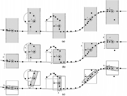
Figure 6 Neighbourhood defined by (a) planimetric distance, (b) 3D distance, (c) distance measured by local surface. Figure courtesy of Filin and Pfeifer Citation(27), © ASPRS.

Figure 7 Typical information for building model generation. (a) Input: original image and point cloud data. (b) Detected 2D line features and 3D planar roof features. (c) Final model with correct topological relations.
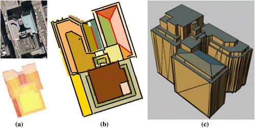
Figure 7 Typical information for building model generation. (a) Input: original image and point cloud data. (b) Detected 2D line features and 3D planar roof features. (c) Final model with correct topological relations.

Figure 8 Regularity definition. Figure courtesy of Pauly and colleagues Citation(30). © 2006 ACM.

Figure 8 Regularity definition. Figure courtesy of Pauly and colleagues Citation(30). © 2006 ACM.

Figure 9 Geometry constraints used to update the quality of connecting edges of buildings. Figure courtesy of Rottensteiner Citation(35).

Figure 9 Geometry constraints used to update the quality of connecting edges of buildings. Figure courtesy of Rottensteiner Citation(35).

Reprints and Corporate Permissions

Please note: Selecting permissions does not provide access to the full text of the article, please see our help page How do I view content?

To request a reprint or corporate permissions for this article, please click on the relevant link below:

Academic Permissions

Please note: Selecting permissions does not provide access to the full text of the article, please see our help page How do I view content?

Obtain permissions instantly via Rightslink by clicking on the button below:

If you are unable to obtain permissions via Rightslink, please complete and submit this Permissions form. For more information, please visit our Permissions help page.