1,288
Views
2
CrossRef citations to date
0
Altmetric
Articles

3D topological relationships of landforms and their spatial schema-based representation

Pages 238-246 | Received 09 Feb 2013, Accepted 20 Aug 2013, Published online: 19 Dec 2013

Figures & data

Figure 1. Sediment cascade of the two subsystems Wall and Talus. Following the notation of system theory (Citation21), no geometry and time is represented (from Ref. (Citation22)).
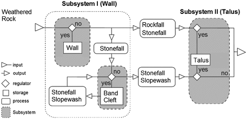
Figure 1. Sediment cascade of the two subsystems Wall and Talus. Following the notation of system theory (Citation21), no geometry and time is represented (from Ref. (Citation22)).

Figure 2. The abstract class _Geoprocess, altering, i.e. creating new instances of the class _State. (modified, see Ref. (Citation23).
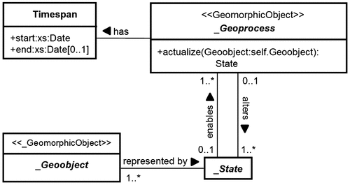
Figure 2. The abstract class _Geoprocess, altering, i.e. creating new instances of the class _State. (modified, see Ref. (Citation23).

Figure 3. Representation of a sediment cascade in 2D. Sediment sources are interpreted as the “from-node” and sinks as the “to-node”.
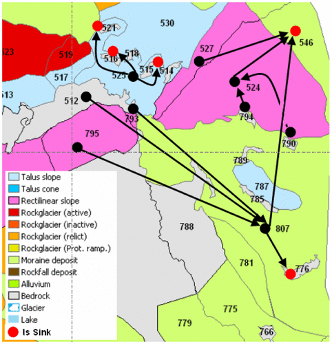
Figure 3. Representation of a sediment cascade in 2D. Sediment sources are interpreted as the “from-node” and sinks as the “to-node”.

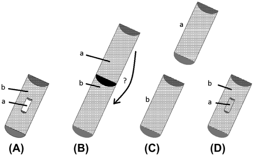
Figure 4. 3D topological relationships of two landforms within a geomorphic system (rf. Table

Table 1. Geomorphic description of topological relationships of landforms (rf. Figure ).
).

Figure 4. 3D topological relationships of two landforms within a geomorphic system (rf. Table Table 1. Geomorphic description of topological relationships of landforms (rf. Figure 3).Download CSVDisplay Table1).

Table 1. Geomorphic description of topological relationships of landforms (rf. Figure ).

Table 2. Geomorphic description of topological relationships of three landforms (rf. Figure ).

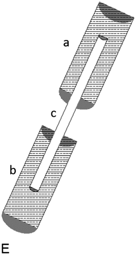
Figure 5. 3D topological relationships of three landforms within a geomorphic system (rf. Table ).

Figure 5. 3D topological relationships of three landforms within a geomorphic system (rf. Table 2).

Figure 6. Differences in the geometric modeling of (a) a natural (buried) feature and (b) a CityGML’s LoD1 building model.
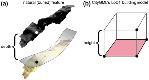
Figure 6. Differences in the geometric modeling of (a) a natural (buried) feature and (b) a CityGML’s LoD1 building model.

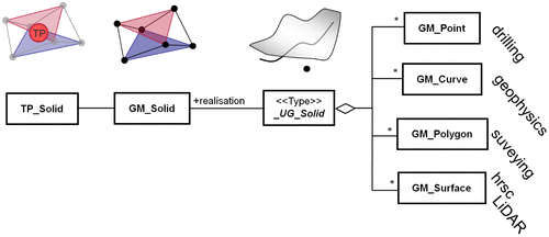
Figure 7. Aggregation of different GM_Primitives to a _UG_Solid.

Figure 7. Aggregation of different GM_Primitives to a _UG_Solid.

Table 3. Possible combinations of simple geometries to form a _UG_Solid.
Reprints and Corporate Permissions

Please note: Selecting permissions does not provide access to the full text of the article, please see our help page How do I view content?

To request a reprint or corporate permissions for this article, please click on the relevant link below:

Academic Permissions

Please note: Selecting permissions does not provide access to the full text of the article, please see our help page How do I view content?

Obtain permissions instantly via Rightslink by clicking on the button below:

If you are unable to obtain permissions via Rightslink, please complete and submit this Permissions form. For more information, please visit our Permissions help page.