Figures & data
Figure 1. IFD flow modeling.
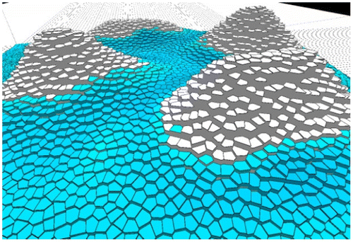
Figure 2. (a) Skeleton between rock types; (b) Labeled points inside polygons; (c) Voronoi cells; (d) Labeled-point Skeleton.
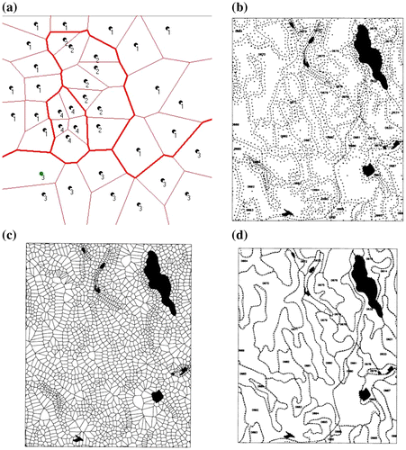
Figure 3. (a) Delaunay plus Voronoi; (b) Crust plus skeleton; (c) Smoothed crust plus skeleton.
Figure 4. Scanned cadastral map: crust and skeleton.
Figure 5. (a) Contour data and Voronoi cells; (b) Interpolated surface with ridges and valleys.
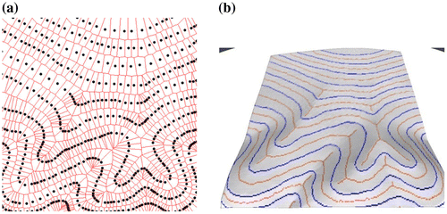
Figure 6. (a) Crust, skeleton, Voronoi cells; (b) Terrain from crust and skeleton; (c) Cumulative catchment areas.
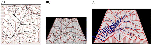
Figure 7. Clusters of roof vector normals (a) on the unit hemisphere (b).
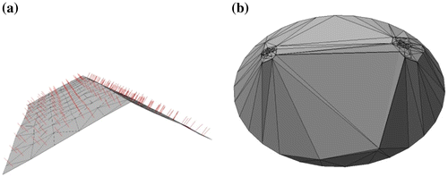
Figure 8. (a) Area-stealing; (b) Natural neighbors.
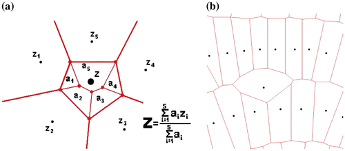
Figure 9. Triangulated terrain: CAD modeling.
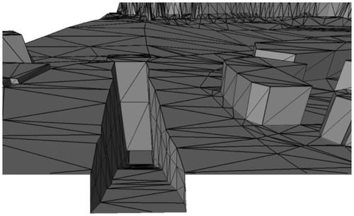
Figure 10. Collision prediction using Voronoi neighbors.
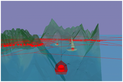
Figure 11. Free-Lagrange model of global tides.
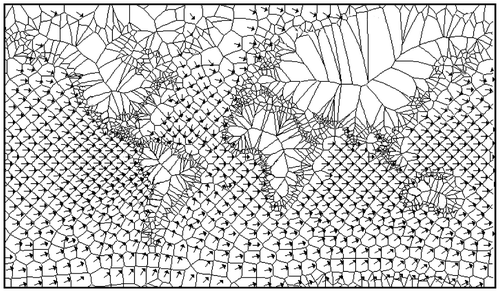
Figure 12. (a) Building outlines; (b) Constrained triangulation.
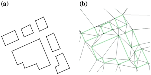
Figure 13. Neighbor relationships from Line-Segment VD.
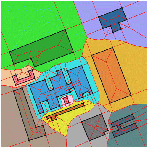
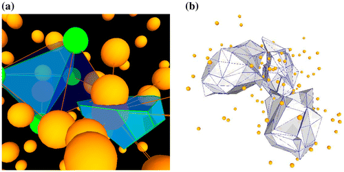
Figure 14. (a) Tetrahedron and 3D Voronoi cell; (b) 3D contour surface.