1,153
Views
1
CrossRef citations to date
0
Altmetric
Articles

Log-cumulants of the finite mixture model and their application to statistical analysis of fully polarimetric UAVSAR data

, , , &
Pages 45-55 | Received 07 May 2017, Accepted 29 Sep 2017, Published online: 09 Feb 2018

Figures & data

Table 1. Key system parameters of the UAVSAR instrument.

Table 2. Texture distributions and log-cumulants.

Figure 1. Matrix variate log-cumulants of mixtures. (a) Mixture of two components. (b) Mixture of three components.
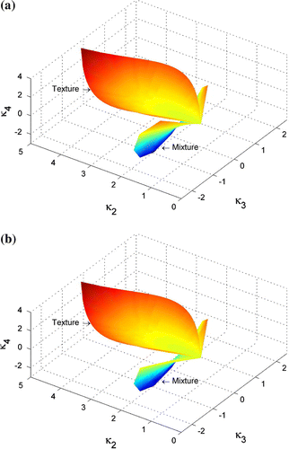
Figure 1. Matrix variate log-cumulants of mixtures. (a) Mixture of two components. (b) Mixture of three components.

Figure 2. Pauli decomposition and ROIs of the first test site.

Figure 2. Pauli decomposition and ROIs of the first test site.

Figure 3. Log-cumulants estimated from different ROIs in the first test site. (a) One perspective of the 3D diagram. (b) Another perspective of the 3D diagram.
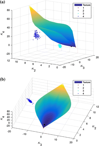
Figure 3. Log-cumulants estimated from different ROIs in the first test site. (a) One perspective of the 3D diagram. (b) Another perspective of the 3D diagram.

Figure 4. Histograms of the intensities from the first test site. (a) ROI 1. (b) ROI 2. (c) ROI 3. (d) ROI 4.
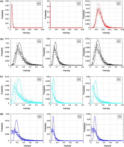
Figure 4. Histograms of the intensities from the first test site. (a) ROI 1. (b) ROI 2. (c) ROI 3. (d) ROI 4.
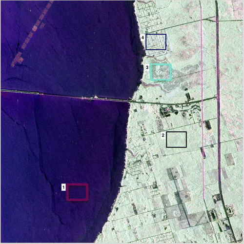
Figure 5. Pauli decomposition and ROIs covering different land types of the second test site.

Figure 5. Pauli decomposition and ROIs covering different land types of the second test site.

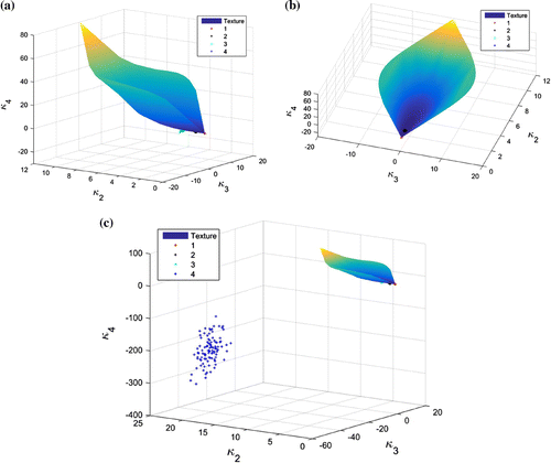
Figure 6. Log-cumulants estimated from different ROIs in the second test site. (a) Different perspective view of the 3D diagram. (b) Different perspective view of the 3D diagram. (c) Different perspective view of the 3D diagram.

Figure 6. Log-cumulants estimated from different ROIs in the second test site. (a) Different perspective view of the 3D diagram. (b) Different perspective view of the 3D diagram. (c) Different perspective view of the 3D diagram.

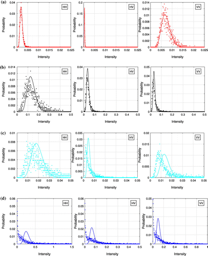
Figure 7. Histograms of the intensities from the second test site. (a) ROI 1. (b) ROI 2. (c) ROI 3. (d) ROI 4.
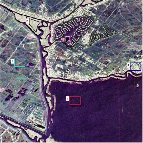
Figure 7. Histograms of the intensities from the second test site. (a) ROI 1. (b) ROI 2. (c) ROI 3. (d) ROI 4.