Figures & data
Figure 1. Adjacency relationships (Lee and Kwan Citation2005)
Figure 2. Topological query (Ying et al. Citation2011a)
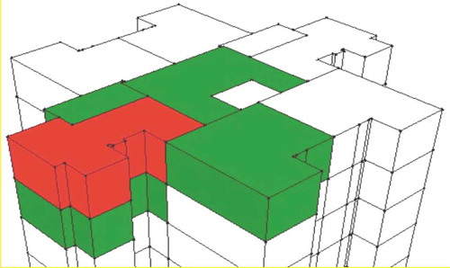
Figure 3. All possible proximity scenarios in voxel (Jjumba and Dragićević Citation2016)
Figure 4. (a) Calculating the center of mass of each face. (b) Creating edges by connecting the corners of each face to the center points. (c) Calculating buffers for each edge
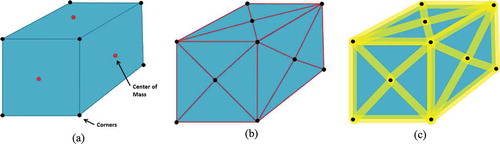
Figure 5. (a) A subject apartment unit with a face and buffered edges. (b) the same apartment unit with some random apartments around it
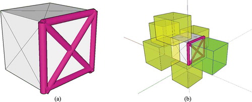
Figure 6. (a) Easement on parking space for accessing the storage. (b) Easement on parking space to give access to a corridor including several storages
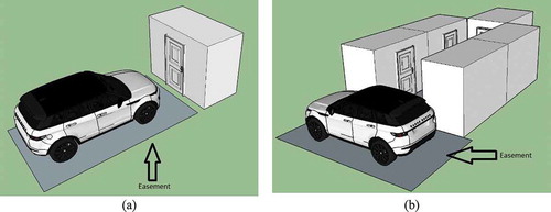
Figure 7. Storages close to parking spaces
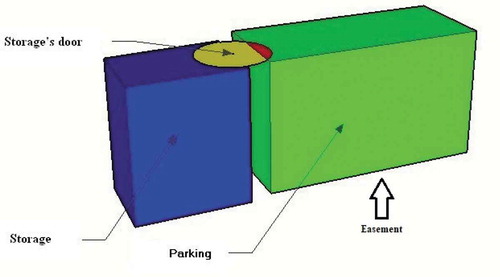
Figure 8. Identify parking spaces that block the corridor accessing the storages
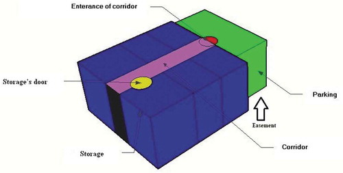
Figure 9. Architectural framework (Arrows indicate the major data flow)
Figure 10. A 3D model of the case study in ArcScene
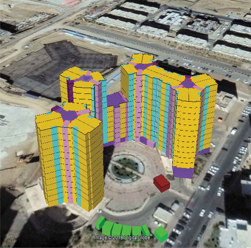
Figure 11. Second basement in a 2D cadastral plan
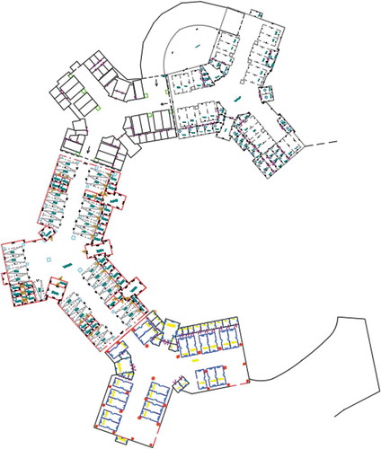
Figure 12. (a) Unconnected lines as part of a polygon in the cadastral plan (b) Related lines were connected to make a polygon after modification
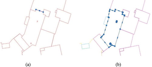
Figure 13. (a) Extruded model. (b) Solid model of the Extruded footprints
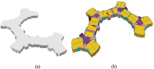
Figure 14. 3D model of high-rises in ArcScene
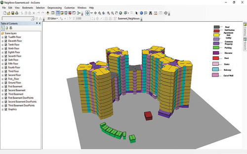
Figure 15. (a) Target apartment unit. (b), (c), (d) & (e) The upper, lower and adjacent neighbors. (f) Results stored in the associated table
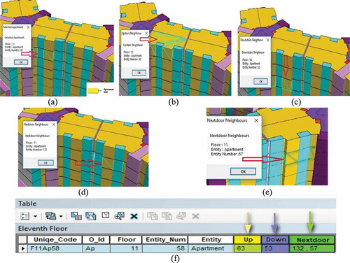
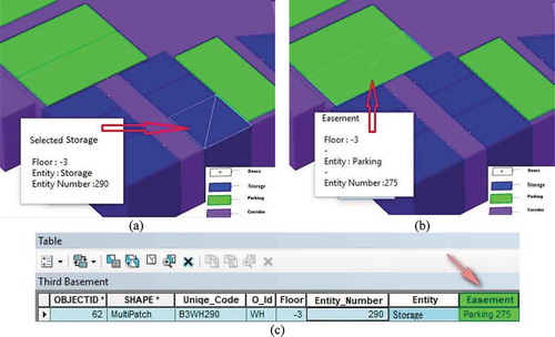
Figure 16. (a) Targeted storage. (b) Identified easement. (c) Results stored in the associated table
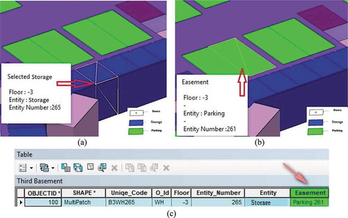
Figure 17. (a) Target storage, (b) Identified easement, (c) Stored results in the associated table