
Figures & data
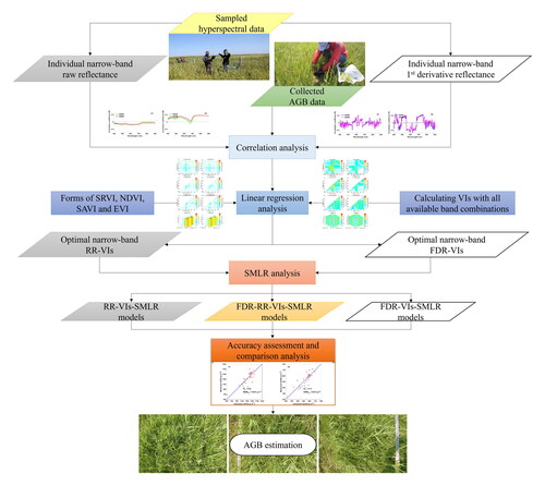
Figure 1. Two experimental sites and sampling points in the study area.
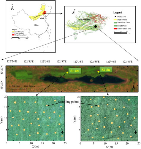
Figure 2. (a) Post level anchored to the spectroradiometer. Schematic diagram of (b) sampling spectral reflectance, (c) cutting grass within the circumscribed quadrilateral of ground-projected FOV, and (d) square field calibration plot and circular ground-projected FOV of each sampling point.
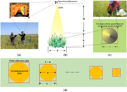
Table 1. Selected VIs used in this study.
Figure 3. Flowchart of data processing and statistical analysis in this study.
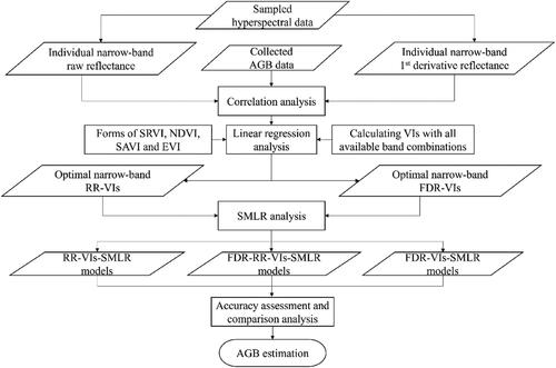
Figure 4. Strategy of dataset segmentation.
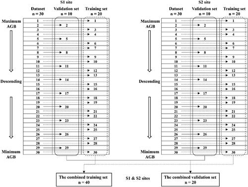
Figure 5. Vegetation communities of the S1 (a, b and c) and S2 (d, e, and f) sites.
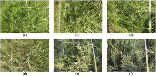
Table 2. Statistic parameters of the aboveground fresh biomass (AGFB) and dry biomass (AGDB) for the S1 and S2 sites, respectively (n = 30).
Figure 6. Correlograms derived from a correlation analysis of the first derivative (upper two figures) and raw reflectance (lower two figures) against AGFB and AGDB at the S1 (left two figures) and S2 (right two figures) sites, respectively.
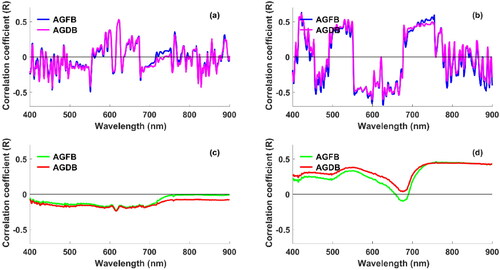
Figure 7. Matrix plots of the coefficient of determination (R2) between FDR-SR, FDR-NDVI, FDR-SAVI and FDR-EVI against AGFB and AGDB at the S1 site.
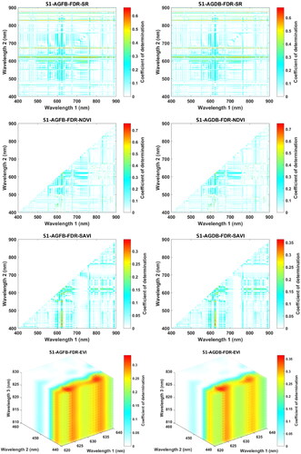
Figure 8. Matrix plots of the coefficient of determination (R2) between RR-SR, RR-NDVI, RR-SAVI and RR-EVI against AGFB and AGDB at the S1 site.
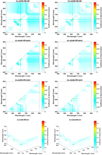
Figure 9. Matrix plots of the coefficient of determination (R2) between FDR-SR, FDR-NDVI, FDR-SAVI and FDR-EVI against AGFB and AGDB at the S2 site.
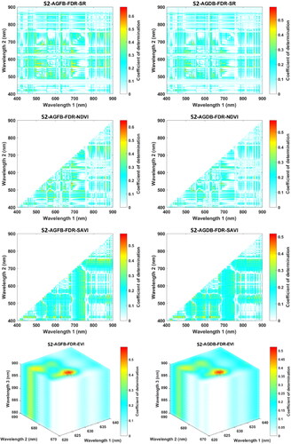
Figure 10. Matrix plots of the coefficient of determination (R2) between RR-SR, RR-NDVI, RR-SAVI and RR-EVI against AGFB and AGDB at the S2 site.
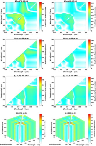
Table 3. Optimal RR-VIs (darker background) and FDR-VIs against AGFB and AGDB based on all possible wavebands at the S1 site.
Table 4. Optimal RR-VIs (darker background) and FDR-VIs against AGFB and AGDB based on all possible wavebands at the S2 site.
Table 5. Results of the SMLR models using best RR-VIs, FDR-VIs, and fused RR- and FDR-VIs with related accuracy parameters for estimating AGFB and AGDB of two sites.
Figure 11. Scattergrams of measured versus estimated AGFB using the recommended FDR-RR-VIs-SMLR model with the combined validation dataset (a), separate validation datasets of S1 site (b) and S2 site (c).
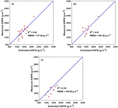
Table 6. Accuracy parameters of the recommended FDR-RR-VIs-SMLR model using the preferred VI variables for estimating AGFB and AGDB.
Data availability statement
The data supporting the findings of this study are available from the corresponding author upon reasonable request.