Figures & data
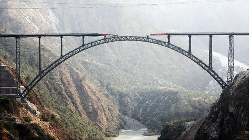
Fig. 1: General arrangement of Chenab Bridge
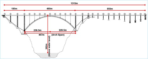
Fig. 2: Transportation of segments. Photo by Chenab Bridge Project Undertaking (U/o AFCONS Infrastructure Limited)
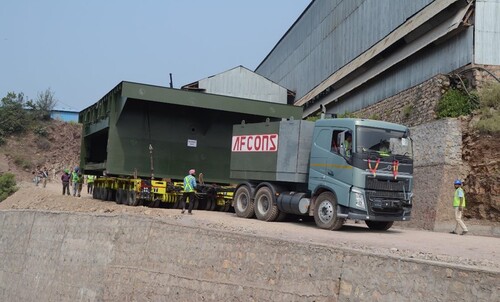
Fig. 3: Before and after excavation for slope stabilization. Photos by Chenab Bridge Project Undertaking (U/o AFCONS Infrastructure Limited)
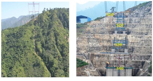
Fig. 4: Arch supported by temporary stays. Photo by Chenab Bridge Project Undertaking (U/o AFCONS Infrastructure Limited)
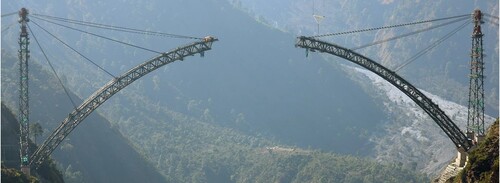
Fig. 5: Temporary tower above pier and 3D model of temporary tower. Photo by Chenab Bridge Project Undertaking (U/o AFCONS Infrastructure Limited)
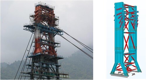
Fig. 6: Three-point lift of arch bottom chord. Photo by Chenab Bridge Project Undertaking (U/o AFCONS Infrastructure Limited)
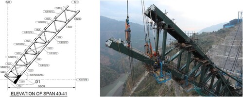
Fig. 7: Snapshot of wind bracings and erected first set of wind bracings. Photo by Chenab Bridge Project Undertaking (U/o AFCONS Infrastructure Limited)
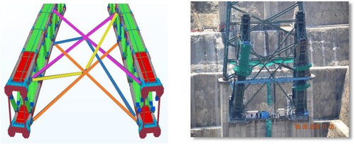
Fig. 8: Arch closure by tripod and telescopic struts. Photos by Chenab Bridge Project Undertaking (U/o AFCONS Infrastructure Limited)
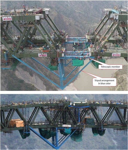
Fig. 9: Incremental launching scheme
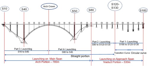
Fig. 10: Launching Platform at S80 and at S10 Location. Photos by Chenab Bridge Project Undertaking (U/o AFCONS Infrastructure Limited)
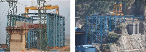
Fig. 11: Incrementally launched deck on combined circular and transition curve. Photo by Chenab Bridge Project Undertaking (U/o AFCONS Infrastructure Limited)
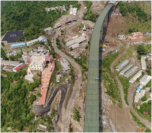
Fig. 12: Deck launching over arch span. Photo by Chenab Bridge Project Undertaking (U/o AFCONS Infrastructure Limited)