Figures & data
Figure 1. The first stimulus (BLUE on the right side) is considered (Stroop) congruent-(Simon) congruent. The next stimulus (RED on the left side) is considered (Stroop) incongruent- (Simon) incongruent. In both cases the correct answer is to push the right button (which is blue) that is highlighted with a dashed line. Only when the word would be written in red should the left button (which is red) be pressed regardless of where (left or right) the word is presented. (B) Location of the fNIRS channels (light dots) on the left cerebral hemisphere. The single dot shows location of the short separation channel. White dots indicate reference points according to the 10/20 system. Dark dotted areas indicate the regions of interest (ROIs): left and right frontal polar area (FPA) or Brodmann area (BA) 10; dorsolateral prefrontal cortex (DLPFC) or BA 9 and 46; dorsal motor cortex (DMC) BA 6 and 8; ventral lateral prefrontal cortex (VLPFC) BA 44 and 45 and ventral motor cortex (VMC) BA 6 and 44. The brain templet was generated using a MATLAB-based toolbox (Singh et al., Citation2005). The axes refer to MNI (Montreal Neurological Institute) coordinate system.
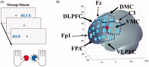
Table 1. Demographic data of participants.
Figure 2. Comparison of the behavioral result from the first and second test sessions. Participants with exhaustion disorder (ED) in full lines with controls in dashed lines. (A) Visual Analogue Scale, (B) Stroop effect reaction time, (C) Error in percent in Stroop–Simon, (D) Omission in percent in Stroop–Simon, (E) Symbol Search, (F) Digit Span total score, (G) Parallel Serial Mental Operation (PaSMO) performance, (H) PaSMO error rate, (I) Speed, divided Attention and Working Memory test (SAWM), (J) SAWM error rate, (K) Digit Symbol Coding (DSC). In figure (B and C) Con represents the congruent stimuli, and in the incongruent stimuli. Data are presented as mean, with standard error of mean (SEM) as error bars. G: significant group effects; T: significant time effects; GvT: significant group vs. time interaction; Stroop: significant Stroop effects. Significant based on FDR adjusted p-value <.05.
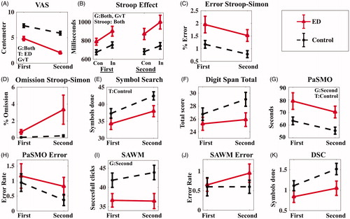
Figure 3. Concentration of oxygenated hemoglobin for the Stroop element of the Stroop–Simon fNIRS task. The data are presented as averages of both the first and second test sessions combined. (A) Each diagram represents a different region of interest in the left or right hemisphere (FPA: frontal polar area; VLPFC: ventrolateral prefrontal cortex; VMC: ventral motor cortex; DLPFC: dorsolateral prefrontal cortex; DMC: dorsal motor cortex). The black bars represent the healthy control group and the red bars are from the ED group. Con represents the Stroop congruent trails, and In represents the Stroop incongruent trials, as described and in the Statistics section. (B) Correlation of oxy-Hb for the Stroop effect (i.e. difference in oxy-Hb concentration between incongruent and congruent trails) with MFS score in the left VLPFC. The error bars are standard error of mean. G: significant group effects; T: significant time effects; GvS; significant Group vs. Stroop effect interaction; S: significant Stroop effects. Significant based on FDR adjusted p-value <.05.
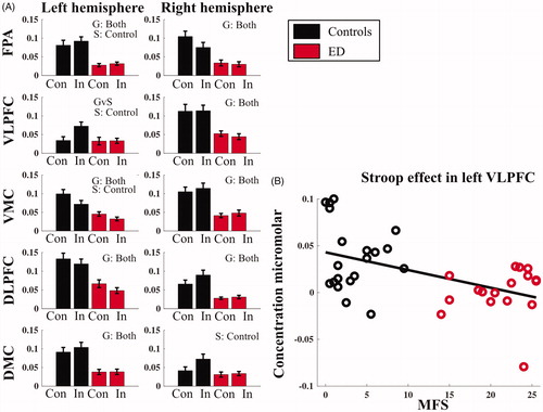
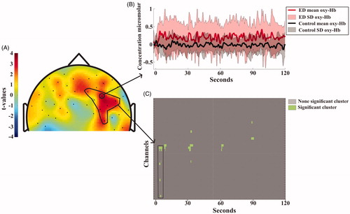
Figure 4. (A) Topographical visualization of activation differences after 100 seconds of the Symbol Search task. Positive t-values indicate higher concentration of oxygenated hemoglobin for ED patients compared to controls. Negative t-values indicate higher concentration of oxygenated hemoglobin for controls compared to patients. The area encircled with a black line in the right DLPFC shows the channel location of the significant cluster, (for detail, see Statistic section). (B) Shows the mean and standard deviation of oxy-Hbchange during the whole test session for each group. The full lines and light field indicate the average oxy-Hb activity and standard deviation for each of the groups. Location of the channel is indicated by the arrow in A). (C) shows the significant clusters. The cluster encircled with the black lines is also depicted in the black marked area in A).
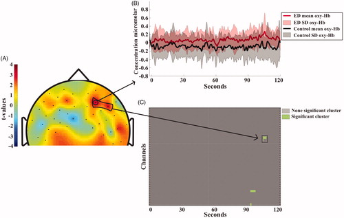
Figure 5. Topographical visualization of activation differences after 5 seconds of the Digit Symbol Coding task. Positive t-values indicate higher concentration of oxygenated hemoglobin for ED patients compared to controls. Negative t-values indicate higher concentration of oxygenated hemoglobin for controls compared to patients. The area encircled with a black line in the right DLPFC shows the channel location of the significant cluster, for detail see Statistic section. (B) Shows the mean and standard deviation of oxy-Hb change during the whole test session for each group. The full lines and light field indicate the average oxy-Hb activity and standard deviation for each of the groups. Location of the channel is indicated by the arrow in A). (C) shows the significant clusters. The cluster encircled with the black lines is also depicted in the black marked area in A).