
Figures & data
Figure 1. Tendon paths of all muscles (a) and the structure of the extensor mechanism of the index finger (b). Gray surfaces represent bone segments; these surfaces are shown for visualization purposes only.
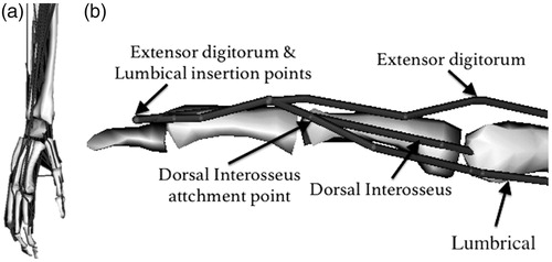
Table 1. Muscle abbreviations.
Figure 2. Theoretically maximum isometric muscle forces and calculated forces in the neutral hand position (joint angles at 0°) and fully flexed position (wrist: 75°, MCP: 90°, PIP°: 101°, DIP: 84°)
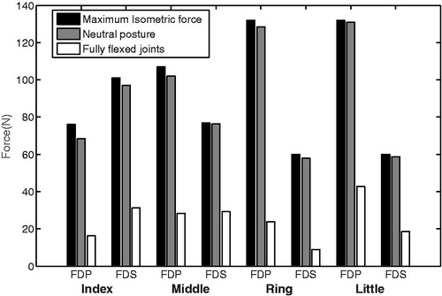
Figure 3. Comparison of model flexion–extension moment arms of MCP joint of the index finger during MCP movement (Model—dashed lines) with those experimentally measured (Exp—solid lines) (An et al. Citation1979). (a) extrinsic muscles; (b) intrinsic muscles.
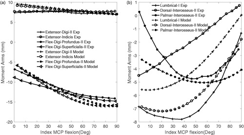
Table 2. Correlation coefficients between model and experimental flexion–extenstion moment arms of the index MCP joint during MCP flexion and of the wrist joint during wrist flexion-extension (p < 0.001) (see Table 1 for abbreviations).
Figure 4. Model (dashed lines) and measured (Exp—solid lines) movement (Brand and Hollister Citation1999, Loren et al. Citation1996) moment arms at the flexion–extension axis of the wrist joint during flexion–extension wrist (see for abbreviations of muscles).
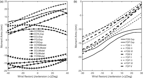
Figure 5. Moment arms of extrinsic and intrinsic muscles as a function of MCP (a, d, g, j), PIP (b, e, h, k) and DIP (c, f, i, l) joint angle.
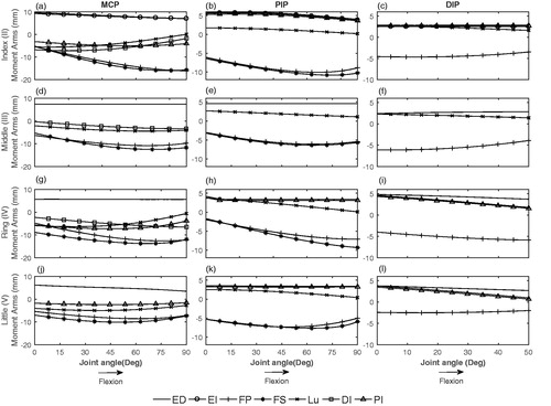
Figure 6. Comparison of FDP and FDS forces of model (dashed lines) and invivo measurement (solid lines) (Kursa et al. Citation2005) during pinch by index finger.
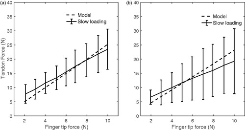
Table 3. Muscle moment arms (mm) at MCP, PIP and DIP joints of the index finger computed by model and experimentally measured (mean ± SD) (An et al. Citation1983).