Figures & data
Table 1. The biomechanical parameters of material.
Figure 1. The seven models of different thread shapes. Model S, Square thread. Model V1, V-thread with thread apex angle 30°. Model V2, V-thread with thread apex angle 60°. Model B1, buttress thread with thread apex angle 15°. Model B2, buttress thread with thread apex angle 30°. Model R1, reverse buttress thread with thread apex angle 15°. Model R2, reverse buttress thread with thread apex angle 30°.
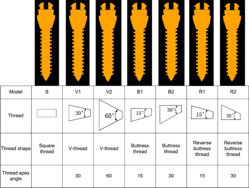
Figure 2. A 6-Nmm torque load was applied in the slot of the top surface of the miniscrew.
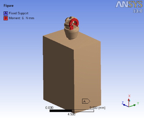
Figure 3. The Max EQV in cortical bone in the seven models. The distribution of maximum and strain throughout the bone adjacent to the miniscrew are presented in the form of color band. The red and the blue color indicate the highest and the lowest magnitude of stress.
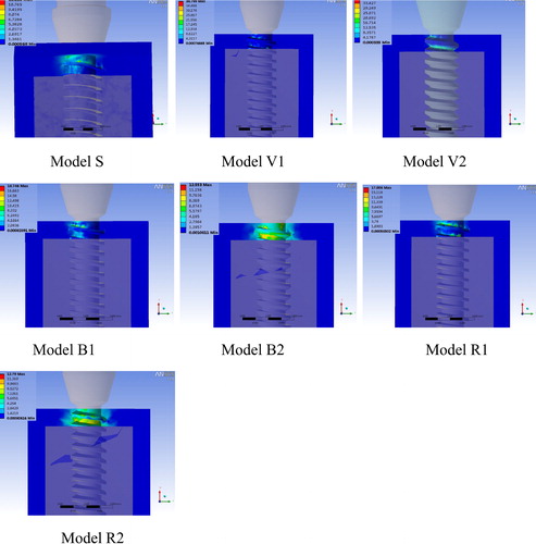
Table 2. The maximum displacement of miniscrew and the maximum equivalent stress of cortical bone in the models with different thread shapes.
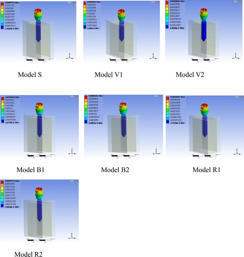
Figure 4. The maximum displacement of miniscrew in the seven models.