Figures & data
Figure 1. The knee joint (a) View of anatomy with complex motion in the sagittal plane (Moser Citation2013); (b) An example of 1DOF hinge knee from ALICE exoskeleton (Cardona et al. Citation2020).
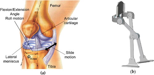
Figure 2. Devices for knee joint taking into consideration its complex motion (a) Example of a device based on a 4-bar mechanism (Poliakov et al. Citation2013); (b) Example of a device based on bone shapes (Hsu et al. Citation2006).
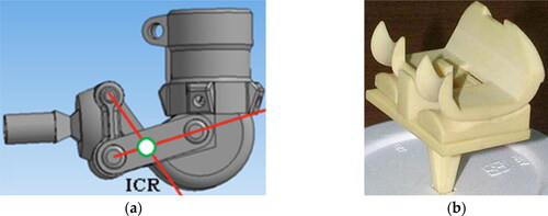
Figure 3. Design of the mechanism’s kinematics (a) Side view with the cam mechanism’s elements and its linear actuator, where: 1 – femur, 2 – tibia, 3, 4 – interchangeable 3D printed elements with cam profiles (b) Cam mechanism’s cross-section with visible ties (5), guides and springs (6) (Kiwała et al. 2018).
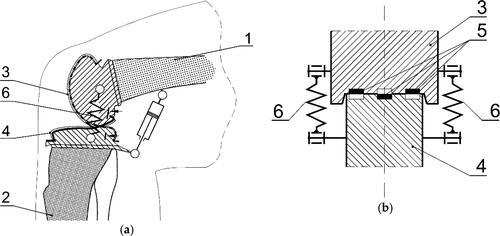
Figure 4. The planned shapes of cooperating cam profiles, fixed centroid for tibia cam (dashed blue line) as from (Bertomeu et al. Citation2007), moving centroid for femur cam (red solid line) obtained from ADAMS.
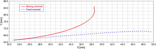
Figure 5. The knee joint cam mechanism prototype’s design as a 3D CAD drawing (a) Front view focusing on the interchangeable cam elements (b) Axonometric view further explaining the working principle by showing the cooperating cam profiles (3,4) and guide grooves (5).
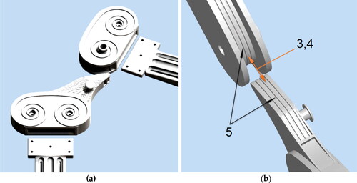
Figure 6. Physical prototype (a) Assembled with i.a. 3D printed elements with placed colour markers (b) Mounted in a stationary frame of the test rig together with the linear actuator, sensors and drawn coordinate systems applied for movements identification and calculations.

Figure 7. Placed on femur markers movements in relation to time (a) Red marker – horizontal x(t), (b) Red marker – vertical y(t), (c) Green marker – horizontal x(t), (d) Green marker – vertical y(t).
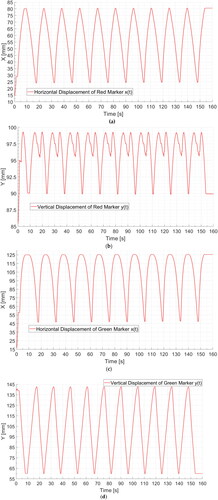
Figure 8. The trajectory of movement y(x) for (a) Red marker (b) Green marker.
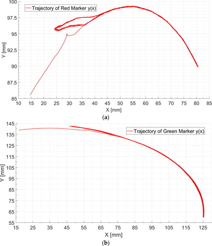
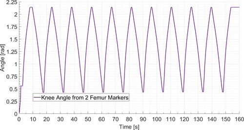
Figure 9. Knee joint flexion/extension angle calculated from the femur markers movement.