7,203
Views
45
CrossRef citations to date
0
Altmetric
Original Articles

A Model for Rolling Bearing Life with Surface and Subsurface Survival—Tribological Effects

, &
Pages 894-906 | Received 31 Oct 2014, Accepted 02 Mar 2015, Published online: 20 Jul 2015

Figures & data

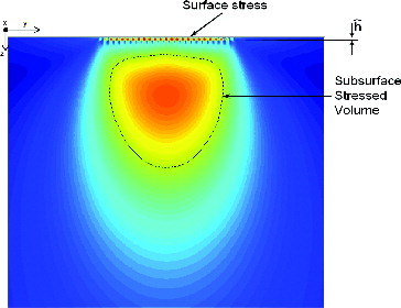
Fig. 1 Schematics of surface and subsurface von Mises stress fields of a Hertzian contact. Surface stresses are related to surface microgeometry and lubrication conditions of the rolling contact. Typically surface stresses are constrained in a narrow layer at the raceway of depth comparable to the surface roughness.
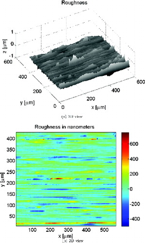
Fig. 2 Inner ring sample roughness of a radial ball bearing 6217, as used in the calculations. The ball surface was assumed smooth.
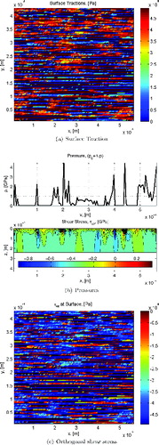
Fig. 3 Calculated surface traction (along rolling direction), pressure, and stress τxz profile at y = 0. Surface stress τxz at overrolling position of maximum mean pressure. Low kappa case, κ = 0.1. Rolling direction from left to right.
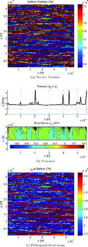
Fig. 4 Calculated surface traction (along rolling direction), pressure, and stress τxz profile at y = 0. Surface stress τxz at overrolling position of maximum mean pressure. High kappa case, κ = 4. Rolling direction from left to right.

Table 1 Comparative Surface and Subsurface Stress Ratios for the Example of the 6217 Bearing, Stress Amplitude (Pa)

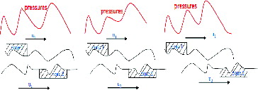
Fig. 5 Illustration of the roughness relative movement inside the contact; the local analysis of the topography is done by varying the mean pressure following to the local Hertz value; see Morales-Espejel and Brizmer (Citation18).
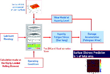
Fig. 6 Flowchart of the advanced surface distress model used to solve the surface related failure modes; see Morales-Espejel and Brizmer (Citation18).

Table 2 Range of Parameters Used in the Advanced Model for Surface Distress for the Derivation of Eq. [Equation31]

Fig. 7 Normalized surface damage function (Rs = IsueLe10.BR/[KLn(1/0.9)]) versus bearing load (P/Pu) and the lubrication conditions (κ) as defined in ISO 281 (Citation15) for conditions of no contamination. Notice that, for higher values of κ better lubrication, the surface damage function is reduced, and it is also nearly constant with load.
Fig. 8 Calculated damage function ratio from Eq. [Equation32] for different κ values and for variable load P/Pu for a deep-groove ball bearing typical case. The importance of the surface damage function with respect to the subsurface is reduced when the lubrication conditions are enhanced.
Fig. 8 Calculated damage function ratio from Eq. [Equation32[32] ] for different κ values and for variable load P/Pu for a deep-groove ball bearing typical case. The importance of the surface damage function with respect to the subsurface is reduced when the lubrication conditions are enhanced.
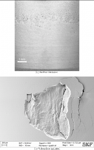
Fig. 9 Pictures of in-house tested bearing raceways showing surface- and subsurface-initiated failures. Overrolling direction from left to right.
Fig. 10 Comparison the surface damage limiting curves of the ball and roller bearings; for example, Eq. [Equation31] and the back-calculated surface damage obtained from endurance testing of bearing population samples.
Fig. 10 Comparison the surface damage limiting curves of the ball and roller bearings; for example, Eq. [Equation31[31] ] and the back-calculated surface damage obtained from endurance testing of bearing population samples.

Table 3 Test Conditions Used for Bearing Life Testing, as Given in (Citation14)

Table 4 Deep-Groove Bearing Example (6309) Results from the Present Approach to Illustrate the Use of the Model