Figures & data
Figure 1. Geometries of a six-start spirally corrugated tube. (a) Geometric model of tube and (b) Geometric parameters of tube.
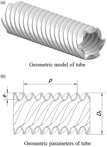
Figure 2. Shell side flow channel model of a six-start spirally corrugated tube.
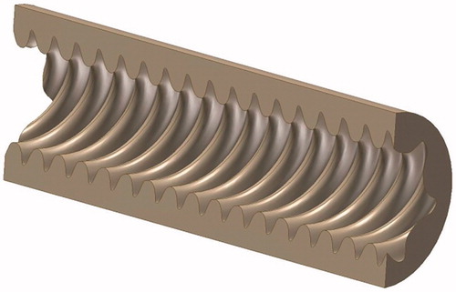
Figure 3. Results of validity verification.
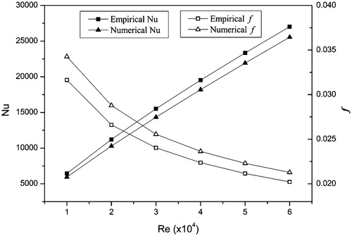
Table 1. Geometric parameters of six-start spirally corrugated tubes with different pitches.
Table 2. Shell side Nusselt number of six-start spirally corrugated tubes with different pitches.
Figure 4. Ratio of Nuc/Nus between six-start spirally corrugated tubes and smooth tubes.
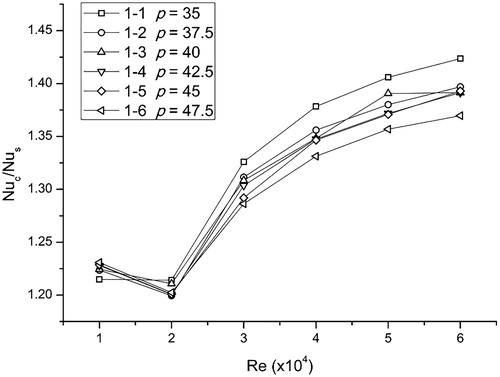
Figure 5. Secondary velocities of six-start spirally corrugated tubes with different pitches.
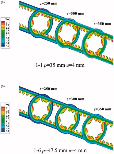
Figure 6. Shell side vorticities of six-start spirally corrugated tubes with different pitches.
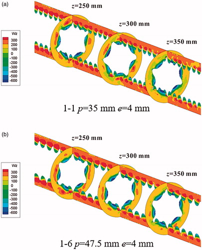
Figure 7. Shell side temperature distribution of six-start spirally corrugated tubes with different pitches.
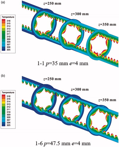
Figure 8. The shell side flow resistance coefficients of six-start spirally corrugated tubes with different pitches.
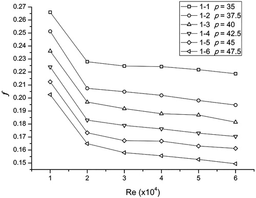
Figure 9. Ratio of the shell side flow resistance coefficient (fc/fs) between six-start spirally corrugated tubes and smooth tubes.
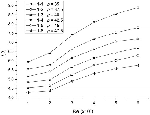
Table 3. Geometric parameters of six-start spirally corrugated tubes with different corrugation depths.
Table 4. Shell side Nusselt number of six-start spirally corrugated tubes with different corrugation depths.
Figure 10. Ratio of Nuc/Nus between six-start spirally corrugated tubes and smooth tubes.
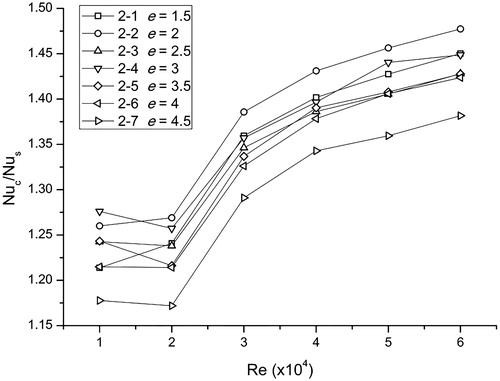
Figure 11. The shell side flow resistance coefficient of the six-start spirally corrugated tubes with different corrugation depths.
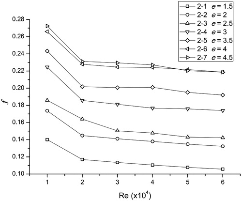
Figure 12. Ratio of the shell side flow resistance coefficient (fc/fs) between six-start spirally corrugated tubes and the smooth tubes (a) Model of Nusselt number (b) Model of flow resistance coefficient.
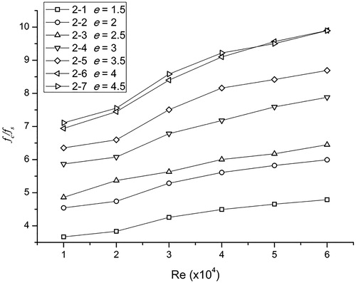
Figure 13. Residual plots of regression models (a) Model of Nusselt number and (b) Model of flow resistance coeffitient.
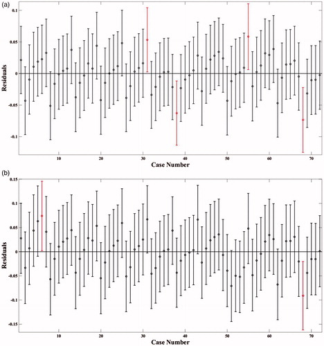
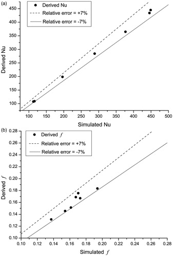
Figure 14. Relative errors between derived and simulaed. (a) Relative errors of Nu and (b) Relative errors of f.