Figures & data
Figure 1. Schematic of computational domain.
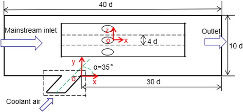
Figure 2. Four-hole configurations.
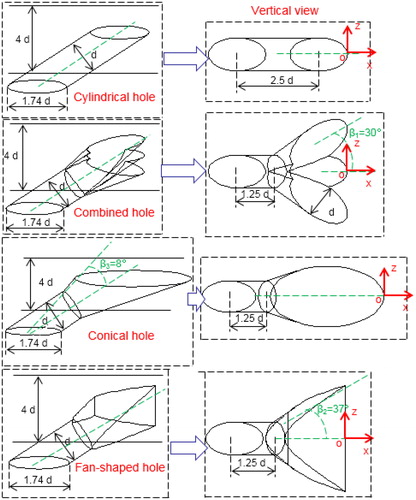
Table 1. Boundary conditions.
Figure 3. Mesh view.
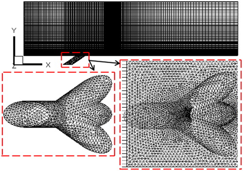
Figure 4. Model validation and grid independence study.
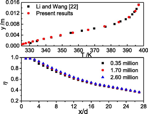
Figure 5. Streamlines and temperature distributions for two hole configurations, M = 1.0.
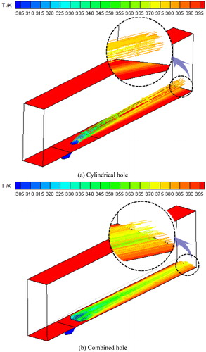
Figure 6. Streamlines and temperature contours on middle sections at M = 0.25 and 1.0.
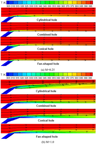
Figure 7. Streamlines and temperature contours on different cross-sections, M = 1.0.
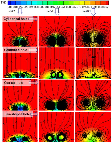
Figure 8. Wall film cooling effectiveness for four-hole configurations with different blowing ratios.
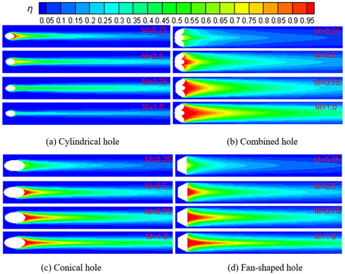
Figure 9. Lateral film cooling effectiveness for four-hole configurations with different blowing ratios, x = 3 d.
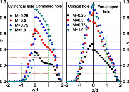
Figure 10. Lateral film cooling effectiveness for four-hole configurations with different blowing ratios, x = 15 d.
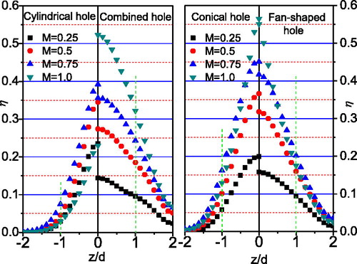
Figure 11. Lateral-averaged film cooling effectiveness for four-hole configurations with various blowing ratios.
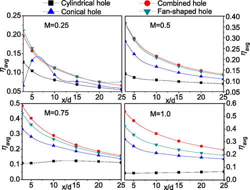
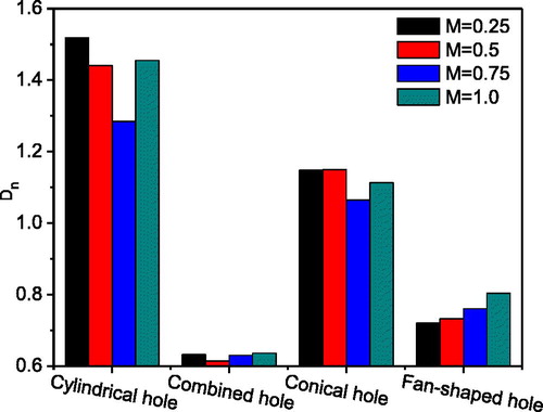
Figure 12. Non-uniformity distribution (Dn) for different hole configurations and blowing ratios.