Figures & data
Figure 1. Computational domain and various arrangements of film cooling holes.
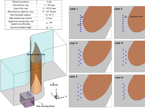
Figure 2. Typical structured meshes in the leading edge region.
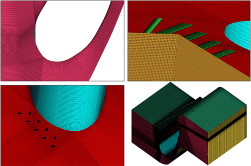
Table 1. Mesh indepence study.
Figure 3. Turbulence model validations: comparisons of pressure coefficients and averaged Stanton number along the streamwise direction.
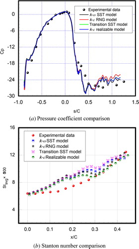
Figure 4. Turbulence model validations: comparisons of endwall film cooling effectiveness.
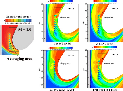
Figure 5. Endwall film cooling effectiveness for different cases at blowing ratio = 1.
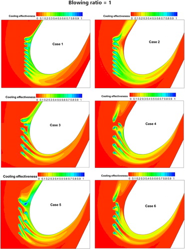
Figure 6. Endwall film cooling effectiveness for different cases at different blowing ratios.
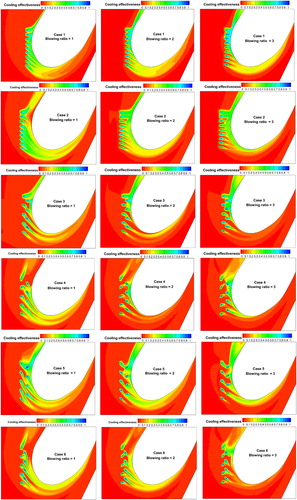
Figure 7. 3-D plot of film cooling effectiveness for different cases at blowing ratio = 3.
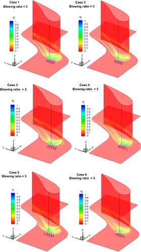
Figure 8. 3-D streamlines from the leading film cooling holes for different cases at blowing ratio = 3.
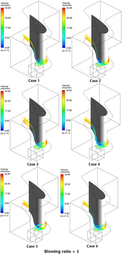
Table 2. Averaged film cooling effectiveness.
Figure 9. Comparisons of averaged film cooling effectiveness in different regions.
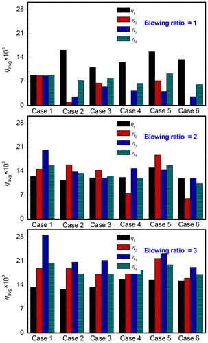
Figure 10. Comparisons of averaged film cooling effectiveness for different cases.
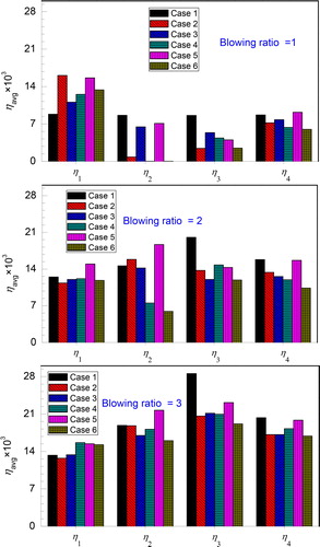
Figure 11. Laterally averaged cooling effectiveness on the endwall at different blowing ratios.
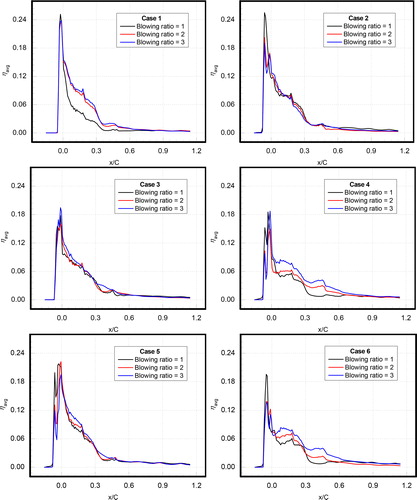
Figure 12. Laterally averaged cooling effectiveness on the endwall for different cases.
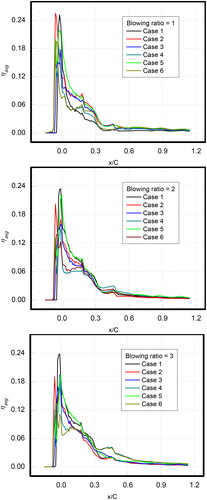
Figure 13. Averaged film cooling effectiveness distributions on the vane surfaces along the spanwise direction at different blowing ratios.
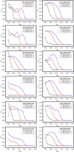
Figure 14. Averaged film cooling effectiveness distributions on the vane surfaces along the spanwise direction for different cases.
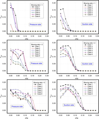
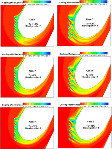
Figure 15. Contours of endwall film cooling effectiveness at different inlet turbulence intensities for Case 1 and Case 5.