Figures & data
Figure 1. Definition of open-loop BDFT and model-based BDFT cancellation
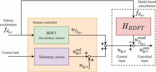
Table 1. Multisine properties used for the disturbance and multisine target signals
Figure 2. Display with the target location path for a single run across the touchscreen for the multisine task
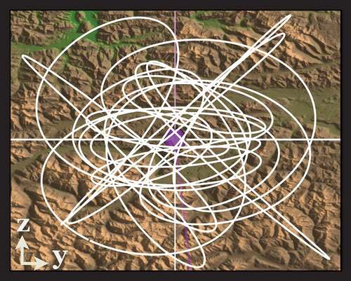
Figure 3. Example target and touchscreen input
time traces for the multisine task
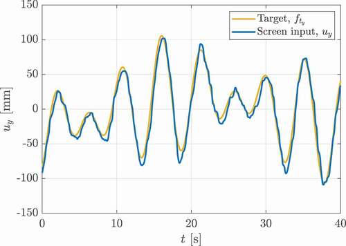
Figure 4. Display with possible target endpoint locations for the step task
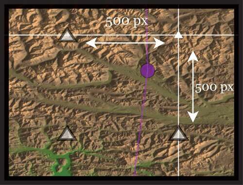
Figure 5. Example target and touchscreen input
time traces for the step task
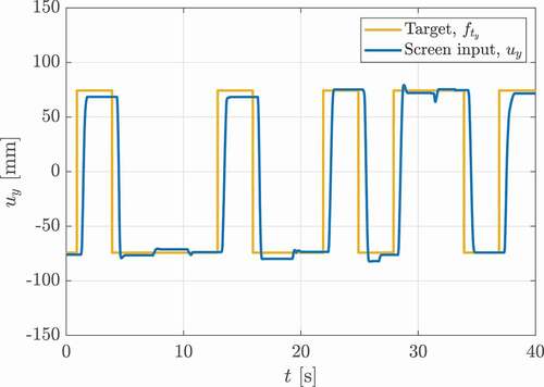
Figure 6. The SIMONA Research Simulator (SRS)
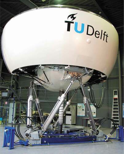
Figure 7. SRS flight deck experiment setup
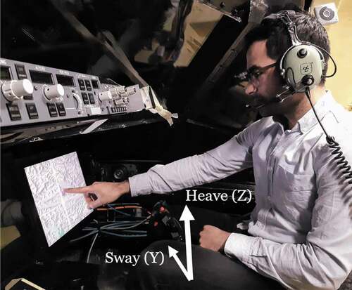
Figure 8. Overview of tested experiment conditions and procedures
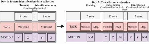
Figure 9. Estimated BDFT model parameters
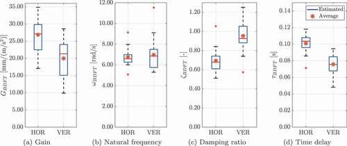
Figure 10. Typical time traces for the multisine task with BDFT cancellation in both the HOR and VER conditions (Participant 1, Trial 1)
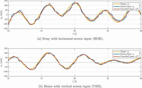
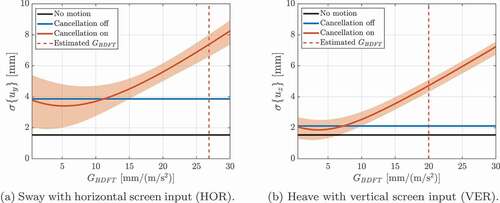
Figure 11. Comparison of the standard deviation of the disturbance component in the input signal for the multisine task
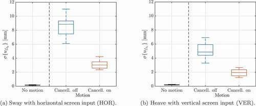
Figure 12. Typical time traces for the step task with BDFT cancellation in both the HOR and VER conditions (Participant 1, Trial 1). The shaded areas indicate the stabilized endpoint data that were used for cancellation assessment
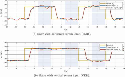
Figure 13. Comparison of step task endpoint variation with and without model-based cancellation
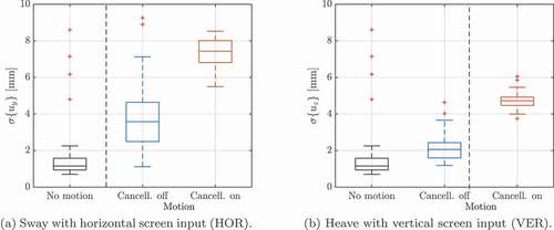
Figure 14. Step task endpoint variation for varying